This thread has been locked.

If you have a related question, please click the "Ask a related question" button in the top right corner. The newly created question will be automatically linked to this question.

BQ76952: BQ76952 does not acknowledge I2C signal in high-side board

Part Number: BQ76952
Other Parts Discussed in Thread: MSP430FR2155, EV2400

Dear TI support team,

I designed two types of BMS board using BQ76952, one is low-side board, means CHG/DSG MOSFET in low-side; another one is high-side board, e.g. MOSFET in high-side. I also use MSP430FR2155 to configure BQ76952 by I2C. As tested, I2C communication in low-side board is no problem, BQ76952 can response and acknowledge I2C signal sent by MCU. Everything is OK.

However, when we tested high-side board, a problem happened that BQ76952 never response and acknowledge I2C signal even in initial power-up stage. We thought it may be due to BQ76952 still not wake-up. So we try to send partial reset signal, e.g. put RST_SHUT  pin less than 1s. It did not work; Short TS2 to ground or putting LD to high also not work. It seems BQ76952 trapped in soft-shutdown mode because REG18 has 1.8V always, no response to RST_SHUT whatever we sent >1s or <1s, no response to I2C.

the following is information of circuit in low- and high-side boards:

1. TS2 has same circuit in low-side and high-side board, e.g. through 10Kohm resistor pull-up to 3.3V

2. In low-side board, LD pin connected to ground through 100kohm resistor, while PACK pin connected to BAT pin through 10kohm resistor.

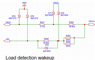
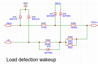
3. In high-side board, LD and PACK pins are connected to Pack+ (input of charger), as shown below. During test, whatever we input Pack+ a high voltage (about 50V) or to ground, the problem was still there.  


Really appreciate for your kind help to find what is issue and provide us a solution!

Thanks!

  • Hello Yanhong,

    Did you capture logic-analyzer images of the communication lines?

    Can you clarify what you mean by TS2 has a 10-kOhm pull-up to 3.3-V?

    What are the differences between both boards? Did you try replacing the IC and see if the issue went away?

    Best Regards,

    Luis Hernandez Salomon

  • Hi, Luis,

    Thank you very much for your fast response! Please see below my answers:

    1, Did you capture logic-analyzer images of the communication lines?

    a. Failed I2C waveforms in high-side board, captured by oscilloscope: yellow-SDA, blue-SCL. This is the first write command. MCU stuck in sending BQ I2C address, because no acknowledge received from BQ.  In this high-side board, there is no any response from BQ. 

    b. Successful I2C waveforms in low-side board: yellow-SDA, blue-SCL. MCU gets acknowledge from BQ, the whole commands can be sent to BQ

    2, Can you clarify what you mean by TS2 has a 10-kOhm pull-up to 3.3-V?

    The above circuit is original design. It works in low-side board. Q44 used in low-side board to wake-up BQ charger. In high-side board, LD pin used to wake-up BQ by charger. It should be mentioned that I removed R272, C78, D69, e.g. TS2 is floating if SW2 not pressed. The problem is still there.

    Another thing is that: before modified, I can measure about 3V on TS2 pin. After modified, e.g. TS2 floating, no voltage can be measured. Is it correct?

    3. What are the differences between both boards?

    No much difference in high-side and low-side board, only MOSFET are driven directly by CHG/DSG in high-board, thus DDSG/DCHG left floating; while in low-side board, DDSG/DCHG and additional drive chips used for MOSFET.

    4. Did you try replacing the IC and see if the issue went away?

    it not easy for us to replace BQ76952, we just try it in same type but different high-side boards, and different type, also high-side boards. The same problem occurred. (We designed two types of high-side: one is current sensing in low-side, another is current sensing in high-side. The exact same problem encountered)

    Thanks! Hope my answers can give you clear picture to help to solve the problem.

    Best Regards,

    Yanhong

  • Hello Yanhong,

    If TS2 is measuring high, it usually indicates the part is in SHUTDOWN, so REG18 is likely 1.8-V.

    If TS2 measures low, the part is in NORMAL mode, or the part is in soft-shutdown. Soft shutdown would occur if TS2 is pulled low and the part is commanded to SHUTDOWN. Here REG18 may measure 1.8-V, but no communications is possible. What cell voltages/stack voltages are you using?

    Where is TS2 in the circuit you shared? What IC are you using? Do you have CRC enabled?

    If you have an EVM or EV2400, are you able to communicate with the IC if you use this instead to connect to your board?

    Best Regards,

    Luis Hernandez Salomon

  • Hi, Luis,

    Thanks for your kind reply! Sorry, I forgot to show TS2 position. Please refer to below figure for better understanding:

    1. Anyway, after I removed R272, C78, D69, Q44 and short D68, e.g. TS2 floating through push-button, TS2 was always low even after issuing shutdown command, e.g. more than 1s high in RST_SHUT pin. BQ did not enter shutdown mode because REG18 still has 1.8V

    2. During test, the cell voltage is about 3.6V, 16S, so stack voltage is about 57.6V, while pack voltage that we input at PACK+ terminal is 59V, about 2V higher.

    3. BQ IC is BQ76952, which has default setting such as: I2C, CRC not enabled, REG1 also disabled.

    4. We did not use CRC in both low-side board and high-side board. For high-side board, since BQ does not response for any I2C signal, we cannot configure BQ registers, so CRC cannot be enabled.

    5. We don't have EVM or EV2400. Currently, we just use on-board MCU to communicate with BQ, while use a debugger MSPFET to program MCU.  

    We are quite confused by such no response from BQ even for RST_SHUT signal, and also its different behaviors in high-side board and low-side board.

    Thanks!

  • Hello Yanhong,

    That is very strange. It sounds like soft-shutdown is happening, did you confirm with a scope that RST_SHUT is being pulled high for longer than a second?

    If TS2 is measuring low, maybe there's something pulling it low, is TS2 completely floating? Could there be something attached to it?

    Best Regards,

    Luis Hernandez Salomon

  • Dear Luis,

    Thank you for your kind support! When I confirmed RST_SHUT pulling high for longer than 1s, I found that REG18 is low. Then I pull TS2 to ground, REG18 became 1.8V again. It means BQ can enter to SHUTDOWN mode. However, after it, BQ still not acknowledge I2C. So I want to check with you:

    1. whether BQ is still in soft-shutdown mode after RST_SHUT >1s -> shutdown -> TS2 pull low?

     2. whether it is necessary to set I2C frequency to exactly 400KHz since BQ setting currently is still in default value?

    3. how do I check BQ operation mode if I2C never successful and REG1 not set?

    Thanks!

    Yanhong

  • Hello Yanhong,

    1. whether BQ is still in soft-shutdown mode after RST_SHUT >1s -> shutdown -> TS2 pull low?
    No, the part is not in soft-shutdown in this case. Soft-shutdown occurs if TS2 is low while the part is trying to enter SHUTDOWN.

    During shutdown, TS2 will be high.

     2. whether it is necessary to set I2C frequency to exactly 400KHz since BQ setting currently is still in default value?
    No, it should not be necessary to be this exact frequency.

    What is your I2C frequency?

    3. how do I check BQ operation mode if I2C never successful and REG1 not set?
    You could use an oscilloscope to read the TS1 pin. This pin by default is a thermistor pin, so you should see this pin pulsing periodically. This would indicate that the part is awake.

    If possible, I'd suggest to get a logic analyzer to better analyze the communications. Additionally, it probably would be good to get an EVM or EV2400 on-hand to test communications with these, to confirm if it could be an issue with the set-up, or microcontroller.

    I would also suggest to do a swap between the IC's of high-side and low-side boards, to confirm the problem follows the IC or it depends on which board it is connected.

    Best Regards,

    Luis Hernandez Salomon

  • Hi, Luis,

    Thanks for your valuable answers! The problem was solved in one of my high-side board, in which current sensing in low-side. Now BQ in this high-side board can acknowledge I2C, settings can be written to BQ's registers!

    However, if current sensing in high-side, in which a TI isolated amplifier, AMC1200BDWVR used to measure the current, its outputs connected to SRP and SRN, BQ cannot enter to SHUTDOWN mode and also cannot acknowledge I2C. I found that the reason was a common mode voltage (about 1.6V) existed in SRP and SRN in this case, because after shorting SRP and SRN to ground, the problem was solved. So, I have some questions, need your help again:

    1. Why does current measurement prevent BQ going to SHUTMODE and make BQ NACK I2C?

    2. What value of common-mode voltage can be accepted by BQ's SRP and SRN pins? If we need high-side current sensing, do you have any circuit recommended?

    3. During testing high-side board, another strange thing is that, if we short PACK+ to Ground, BQ internal temperature will be increased and BQ became hot. Actually, since we just tested BQ functions, this PACK+ did not connect to actual charger or load, only a DC power supply with low current (1mA limit) applied to PACK+. The circuit is shown below. 

    Why BQ's internal temperature increased in this case?   

    4. If battery cells removed, e.g. Cell16 is zero, but voltage in PACK+ is still there, we found BQ still working and voltages in REG18 and REG1 are normal. We are also confused by this phenomenon, because Cell16 is zero, no current provided to REG1. 

    Who provides such voltage and current to REG1? Please refer to below fig. for BQ circuit.

    Thanks! Looking forward to your kind support!

    Yanhong

  • Hello Yanhong,

    Ah! I see now what is going on! This device does not support high-side current sense by default. Typically these should be kept close to the Vss level for them to work correctly. 

    1. Why does current measurement prevent BQ going to SHUTMODE and make BQ NACK I2C?

    A high enough common-mode voltage in both SRP and SRN can cause unintended behaviors in the part.

    2. What value of common-mode voltage can be accepted by BQ's SRP and SRN pins? If we need high-side current sensing, do you have any circuit recommended?

    Typically these should be close to Vss when there is no current flowing. We would recommend that there isn't any common-mode voltage on the SRP/SRN pins, as these were designed with them being close to Vss.

    3. During testing high-side board, another strange thing is that, if we short PACK+ to Ground, BQ internal temperature will be increased and BQ became hot. Actually, since we just tested BQ functions, this PACK+ did not connect to actual charger or load, only a DC power supply with low current (1mA limit) applied to PACK+. The circuit is shown below. 

    Were the FET's ON or OFF during this test? Did you measure the voltage drop across the resistors to see if there was any voltage drop across them?

    4. If battery cells removed, e.g. Cell16 is zero, but voltage in PACK+ is still there, we found BQ still working and voltages in REG18 and REG1 are normal. We are also confused by this phenomenon, because Cell16 is zero, no current provided to REG1. 

    Who provides such voltage and current to REG1? Please refer to below fig. for BQ circuit.

    It could be possible that this is happening due to the CHG driver connection. If the CHG FET is OFF, it connects internally to the BAT pin. So a voltage applied from PACK+ could reach the BAT pin in this case. That's a thought. You could measure the BAT pin and see if there's a voltage.

    Best Regards,

    Luis Hernandez Salomons

  • Hi, Luis,

    Thank you very much for your kind support! Now I have a better understanding of this BQ IC.

    As for my previous question No.3, is it due to LD sending current from BQ to check load status? My test condition is in normal mode, e.g. both CHG/DSG FET on. But no real current flowed through FET, just for function test. The voltage drop I measured from LD pin to PACK+ terminal was 52mV, which means about 5.2uA current flowing from BQ. Does it cause BQ internal temperature rising, up to 65 deg C? Does it damage IC?

    Regarding to question 4, I checked that BAT still had voltage, even after I removed battery cell and leaved PACK+ voltage there. The voltage value are as following:

    PACK+: 56V

    BAT: 46.4V

    CHG: 46.7V

     CP1: 57.6V

     Then, I checked datasheet, pg33, 8.2, and found that both BAT and PACK provide voltage to CP1, is it possible the BAT voltage from CP1? 

    Thanks!

    Best Regards,

    Yanhong

  • Hello Yanhong,

    No, 5.2-uA should not enough to cause that much temperature to rise. I'd suggest to measure currents around the IC and see if you find any large currents flowing. Is there any current flowing out of the LDO's for example?

     Then, I checked datasheet, pg33, 8.2, and found that both BAT and PACK provide voltage to CP1, is it possible the BAT voltage from CP1? 

    It may be possible yes. I would imagine that either through the charge-pump or the CHG pin (When CHG is OFF)

    Best Regards,

    Luis Hernandez Salomon