This thread has been locked.

If you have a related question, please click the "Ask a related question" button in the top right corner. The newly created question will be automatically linked to this question.

TPS61022: Maximum Output Current

Part Number: TPS61022

Hello!

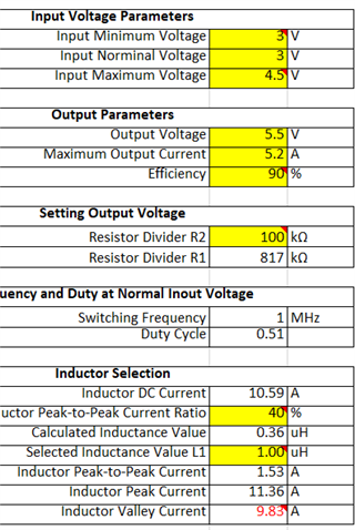
In our application we are feeding the TPS61022 from a single 18650 battery ("Nominal" 3.6V cell, but will drop as it discharges). The 61022 output voltage is set for 5.5V. Our maximum output current peaks are 5.2A.

We are planning to use the Coilcraft XAL6030-102MEC inductor referenced on page 15 of the datasheet.

Do you see any issues with utilizing the 61022 to supply this level of output current?
If so, please advise any issues or suggestions.

Related - I'm not completely clear how the valley current limit is related to the maximum output current.


Thanks and Best Regards
Jerry Molnar

  • Hi Jerry,

    You can use the calculation tool in ti.com to evaluate the max output current of TPS61022.

    You can find that with VIN=3V, VOUT=5.5V, IOUT=5.2A, the valley inductor current is 9.83A (assume eff = 90%), it is larger than the min valley current limit (6.5A) of TPS61022.

    So it can't support 5.5V/5.2A from 3V input. You needs to reduce the output current until the valley inductor current is smaller than the min valley current limit.

    Regards,

    Nathan

  • Hi Nathan,

    Thanks for your sobering :-) reply! Somehow, we missed seeing that tool and we also had scope creep increase the current requirements.

    I've been able to remove quite a bit of the load current via selecting some different relays. The max current is now 4A.
    Using the spreadsheet and the new load current, the numbers fall under the lowest valley current limit.

    I have 2 further questions:
    [1] Junction Temp - For the 5.5V output with a 4A load current and 90% efficiency, I'm estimating that the device will be dissipating about 2W. The operating ambient of the product is 15C-30C.
    Do you have any special recommendations re the layout to help with heat dissipation? We are planning to follow the layout in figure 10 of the SLVAES4 (The 61022 Layout Guidelines doc).

    [2] The valley current spec; instantaneous vs average current -

    In our application, the max load current is made up of some constant DC loads (e.g. relays) and some load currents that are PWM regulated. Specifically there are some heater elements that are pulse width modulated at 1Khz, with a varying duty cycle (e.g. a transistor turning them on/off at the 1KHz rate).
    To arrive at the maximum current the 61022 has to supply, I used the peak instantaneous current that the heaters consume. For example, if the heater has a resistance of 5.5 ohms, then the instantaneous peak current when it is on is 1A.  However if the duty cycle is 30%, the average current is 300ma.

    My question is related to how the valley current spec is arrived at - is it simply the max (peak) current that can flow in the path (e.g related to the size of device on the die) or is it average heat on the die. If it was the latter that would be more related to our average current draws.

    Thanks for all your help!
    Jerry Molnar

  • Hi Jerry,

    1.You can refer to the Section 6 of SLVAES4 about the general thermal improvement method.

    My question is related to how the valley current spec is arrived at - is it simply the max (peak) current that can flow in the path (e.g related to the size of device on the die) or is it average heat on the die.

    2.The first one, the max current limit is not related to thermal. So generally TPS61022 will hit current limit at first not thermal shutdown, unless the operating ambient temperature is very high, etc Ta=100C.

    Regards,

    Nathan

  • Thanks for you support Nathan! Very much appreciated.

    Best Regards
    Jerry Molnar