This thread has been locked.

If you have a related question, please click the "Ask a related question" button in the top right corner. The newly created question will be automatically linked to this question.

TPS55289: Operating mode and I2C address setting on WEBENCH

Guru 12000 points
Part Number: TPS55289

Hi,

Question 1
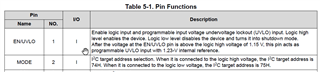
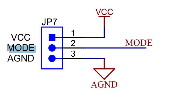
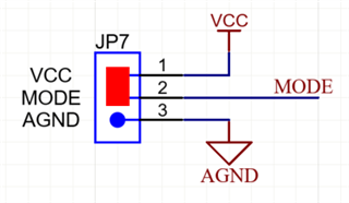
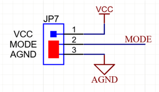
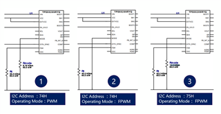
When I set the I2C address to 74H and executed WEBENCH, a configuration was generated in which the MODE pin was connected to GND as shown in ② below.
The pin function in the datasheet states that when setting it to 74H, it must be set to High. Should I prioritize the contents of the datasheet for reference instead of WEBENCH?

Question 2
The data sheet states that the MODE pin is used to set the I2C address. As shown in ① and ③, Rmode with different constants were connected in the settings on WEBENCH.
What does this difference in resistance constant mean?

Question 3
We are considering using a configuration that VIN = 5V to 24V and VOUT=5V. If you have any concerns when VIN=5V and VOUT=5V, please let us know.
I am concerned that there may be abnormal behavior when VIN=VOUT.

Thanks,

Conor

  • Hi Conor,

    Thanks for reaching out.

    1. Sorry, there may be some error on Webench simulation, please always keep the datasheet as the first reference.

    TPS55289 uses MODE pin to select I2C target address, and when it is connected to low, the I2C target address is 75H.

    2. There is no problem when Vin=5V and Vout=5V. When the input voltage is close to the output voltage, this device will work in Buck-boost mode and TPS55289 alternates between one-cycle buck mode and one-cycle boost mode.

    BRs,

    Bryce

  • Hi Bryce,

    Thank you for your reply.

    Question 2
    The data sheet states that the MODE pin is used to set the I2C address. As shown in ① and ③, Rmode with different constants were connected in the settings on WEBENCH.
    What does this difference in resistance constant mean?

    What about Q2? Different Rmodes are connected, does it mean anything?

    On the EVM circuit diagram, it seems that no pull-up or pull-down resistors are inserted.

    Thanks,

    Conor

  • Hi Conor,

    Thanks for pointing it out. There should be some mistake with the Webench model. Please always keep the datasheet as the first reference.

    In the EVM, we have the jumper to connect 1pin and 2pin of JP3 to set MODE=High, or connect 2pin and 3pin to select MODE=Low.

    BRs,

    Bryce

  • Hi Bryce,

    Therefore, are pull-up and pull-down resistors not necessary?

    Thanks,

    Conor

  • Hi Conor,

    The pull-up resistor or pull-down resistor is not necessary, you can choose either fig1 or fig2 to select the corresponding I2C address.

    Fig 1.

    Fig 2.

    BRs,

    Bryce