This thread has been locked.

If you have a related question, please click the "Ask a related question" button in the top right corner. The newly created question will be automatically linked to this question.

UCC256404: Audible Noise after connecting PFC

Part Number: UCC256404
Other Parts Discussed in Thread: UCC28180,

Hello,

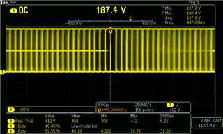
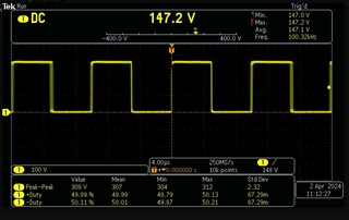
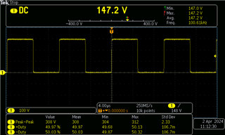
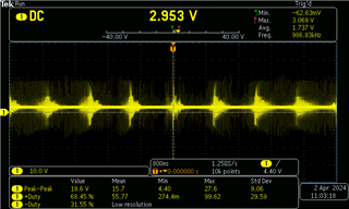
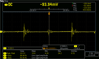
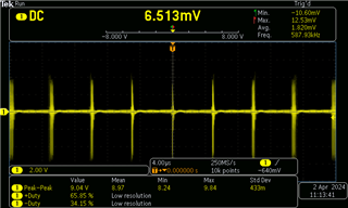
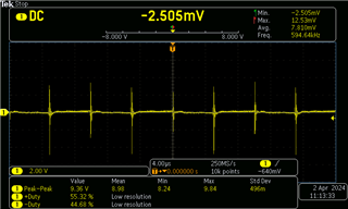
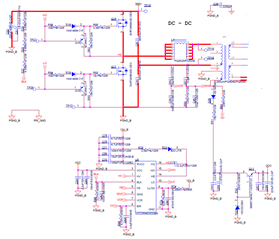
We are getting audible noise once we connect the UCC256404 with the UCC28180 PFC 390V. System works fine when the LLC works without PFC at 320V instead of PFC 390V. We are not getting noise even if we load the PFC only without LLC. Problem starts only if we connect the both PFC & LLC. PFC VCC will be getting power from the RVCC of UCC256404. We done the design like Eval PMP40766 but output voltage will be 29.2V & 900W.

Pease help me out of this problem...


Kind Regards,

Nishanth M

  • Hi Nishanth,

    Could you share the VCR, HS, ISNS waveforms. At what load, you are hearing this noise> What's the burst entry level for this 900W design?

    Regards

    Manikanta P

  • Hi Manikanta,

    Thanks for the support...

    Noise starts from 1A load onwards at the secondary side. LLC Top & Bottom Mosfet fails after 45 minutes of 900W 30A full load operation. Tomorrow we will share the waveforms of VCR, HS, ISNS asap. 

    Kind Regards,

    Nishanth M

  • Will be waiting for your waveforms. Did you do the temperature measurement of your prototype to see which is creating more losses?

    Regards

    Manikanta P

  • Hi Manikanta,

    Thanks for waiting for my reply and support...

    Yes, I did the temperature measurement, but all the components are in normal range <45 degrees Celsius. Only LLC transformer will making noises once we connect the PFC and Mosfets will fail after 35 ~ 40 minutes. There is no problem when we load LLC without PFC.

    Check out the waveforms of the VCR, HS, ISNS. Due to PFC switching noise all the signals are disturbed. 

    Note:

    1. Run --> Waveforms captures at DSO Run Mode.

    2. Stop -->Waveforms captures at DSO Stop mode or Single Capture waveforms captured. 

    HS Run Mode with PFC ON

    HS Stop Mode (Single) with PFC ON

    HS Run Mode with PFC OFF

    HS Stop Mode (Single) with PFC OFF

    VCR RUN PFC ON

    VCR STOP (Single) PFC ON


    VCR RUN PFC OFF

    VCR STOP (Single) PFC OFF

    ISNS RUN PFC ON

    ISNS STOP (Single) PFC ON
    ISNS Stop PFC ON

    ISNS RUN PFC OFF

    ISNS STOP (Single) PFC OFF

    Please check and help me out of this issues...

    Regards,

    Nishanth M

  • Hello,

    I have received your inquiry and it is under review.

    Regards,

  • Hello,

    I reviewed the data sheet for this device and it has input over voltage protection.  If the design works fine at 340 V and does not work o.k. at 390 V it could be triggering the input OVP.  You might want to look at the BW pin to see if this is what your issue is.

    I do have recommendations while you are trouble shooting.  I would use a DC supply for the input of the LLC until you have debugged to work at 390 V.  After that you can add a DC supply. 

    Regards,

  • Hello,

    We given the AC input from the step up transformer to get 390V DC Bus supply. We noticed that LLC is generating the noise once the Bus voltage reaches to above 360V DC. So we changed the values of the LL/SS resistor divider network and BW pin of LLC IC. We made the Burst Mode to Option 7 (Disable Burst). After changing the values, the audible noise and electrical nose had been arrested. But now new problem had been created such that UCC256404  is taking more current from VCC which is generated from the Post Regulator of the the Bias Winding. Bootstrap diode US1M & Series resistor 2.2E is getting heated up and failing after once the converter reaches the 50% load. After changing all the values now currently converter is working with the PFC without any audible noise but bootstrap driving problem had been started. So please help me out of this problem...

    LL/SS: 

    1. Top Resistor:91K

    2. Bottom Resistor:36K

    3.Parallel Capacitor: 470nF

    BW:

    1. Top Resistor: 51K

    2. Bottom Resistor: 3.3K

    3.Parallel Capacitor 100pF

    Kind Regards,

    Nishanth M

  • Hello,

    The boot strap diode D23 and R75 should not be getting hot.  Did you use a fast recovery diode for D23? 

    Could you double check this?

    If you used a slow recovery diode it would cause this resistor and diode to over heat.

    Regards,

    Mike

  • Hi, 

    Yes, I tried with ST Diode ultra fast 600V 2A STTH2R06S. Still the diode is heating….Initially I used 1000V 1A US1M diode and I changed to ST. When I turned ON the converter with load connected of 10A during that time low side mosfet fails. Check and help me out of this issues….

    Kind Regards,

    Nishanth M

  • Hello,

    It seems that the FETs you are driving might be requiring too much current.   Generally to drive FETs will take 20 mA of DC current to drive them.  The power dissipated by the diode should be less then 40 mW.  So if it is getting hot there is too much current going through it.  

    You could try FETs FETs with lower gate capacitance to reduced boost diode loading and reduce heating.

    Another thing that you can do to cut your current losses in half is to go with a Schottky diode instead of an ultra fast rectifier.

    Regards,

  • Hello,

    Thanks for the reply.

    We are using less Qg and Capacitance Mosfet only comparing to TIDA-010081 design LLC Mosfet. Bootstrap circuit is only for high side Mosfet driving but why the low side Mosfet fails.

    TK190E65Z - Mosfet which we are used and TK040N65Z - which is in TI Design. 

    Will you check and tell me my LL/SS & BW values are correct. After changing these values only Noise arrested but the bootstrap problem started.

    LL/SS: 

    1. Top Resistor:91K

    2. Bottom Resistor:36K

    3.Parallel Capacitor: 470nF

    BW:

    1. Top Resistor: 51K

    2. Bottom Resistor: 3.3K

    3.Parallel Capacitor 100pF

    For you information, We don't need the burst mode for my application.

    I am unable to send direct message to you for sharing the UCC256404 design excel sheet.

    Kind Regards,

    Nishanth M

  • Hello,

    I thought just your boot strap diode and resistor were the only ones that were getting hot.  If you low side MOSFET is failing it is most likely due to over current.  This could be due to an incorrect Isense divider setup and resistor value.

    I would double check your ISNS resistor and divider network with the excel tool to make sure they are the correct values.   You should be within +/- 1% of the recommended values.

    Regards,