This thread has been locked.

If you have a related question, please click the "Ask a related question" button in the top right corner. The newly created question will be automatically linked to this question.

UCC25660: ucc25660

Part Number: UCC25660
Other Parts Discussed in Thread: UCC28180, UCC256402, UCD3138
Dear TI team ,
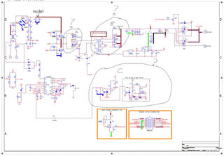
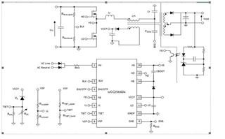
we have designed a schematic of 504 watt (84v-6a) and 1200 watt(64v18.5A) llc only with UCC25660 ic, can you please verify our schematic and design tool.
Please find the attached file.
Application :- EV charger 

Thank 

Aditya arya 

  • OK, I will let you know my feedback.

  • Hi Aditya,

    Could you reduce the Lm/Lr ratio to reduce the change in frequency variation when input and output voltage changes. you can start with a ratio of 3. That also helps to achieve ZVS.

    Please share the design collectors with the updated values.

    Regards

    Manikanta P

  • Dear manikanta ,

    Sir, if possible can you modify the tool as per the requirement of our application, I am sharing the details

    Application:- EV charger 1200watt  

    Ac input voltage  :- 170V-265V

    Dc output voltage  :- 64V

    Dc output current :- 18.7A

    output power max:- 1200Watt

    Efficiency :- 90%

    Application:- EV charger 504watt  

    Ac input voltage  :- 170V-265V

    Dc output voltage  :- 84V

    Dc output current :- 6A

    output power max:- 504Watt

    Efficiency :- 90%

    Thanks

    Aditya arya

  • Hi Aditya,

    I would recommend you to design and simulate the power stage across load/input voltage range before building the prototype. The issue is that, The power stage components that I select might not be available to purchase.  I can definitely review them

    Could you let me know why LLC is chosen for 1.2kW design. Usually, we recommend Phase shifted Full bridge controller  (UCC28951 data sheet, product information and support | TI.com) for above 1kW designs.

    Regards

    Manikanta P

  • Dear manikanta ,

    we chose this LLC controller because it is cost effective, as per your suggestion please modify the tool for 1k.w(64v-15.6a). And for 504watt(84v-6A) and power component we can manage or we can use that tool as reference. And we modify according to the available power components.

    Please also verify the schematic I shared

    Application:- EV charger 1000watt  

    Ac input voltage  :- 170V-265V

    Dc output voltage  :- 64V

    Dc output current :- 15.6A

    output power max:- 1000Watt

    Efficiency :- 90%

    Thanku

    Aditya arya

  • Hello Aditya,

    The following link will bring you to the excel design tool for the UCC25660 devices.  You can use this tool to select the components need for an LLC design to meet your specifications.

    https://dr-download.ti.com/design-tools-simulation/calculation-tool/MD-2ms9HcHm1B/1.0/UCC25660x_CALC_1.0.xlsx

    After reviewing your power requirements more than likely you need a PFC front for the design.  You might consider using the UCC28180 and designing a PFC front from your AC input to 390 V DC and then designing the LLC for 390 V down to 64 V.  The following link will get you to the product folder for the UCC28180 where you can find application notes and design tool on how to design a PFC boost front end.  If you have questions on this device please  post on the e2e so the appropriate applications engineer can answer your questions.

    https://www.ti.com/product/UCC28180

    I have another suggestion for you as well.  You might want to search the reference design library to see if there is an existing reference design that already meets your power requirements.  The following link will bring you to the reference design library and just enter your input and output power requirements and the tool will find designs that are closest to your power requirements that you can use. 

    https://www.ti.com/reference-designs/index.html

    Regards,

  • Dear Manikant  P
    We want to pursue further not just keep sitting and exchanging reply 

    1. i shared you design tool filled by me in my first post , if you really have some suggestions please change there and send back. its same tool which you are referring today. repeating again - you have our filled tool , sch , design requirement , please share back modification in tool and suggestion on sch

    2. noted your suggestion also to use pfc so preparing another design also , but first we will try without pfc.

    please support 

  • Hello Aditya,

    I believe that having a PFC front end will be the most efficient approach for your design due to the wide input range.

    If you chose to do this I reference the excel design calculator for a PFC pre-regulator using the UCC28180.

    The second thing that I advise that you do is to redesign the LLC for the 390 V input that comes from the PFC.

    You will just need to modify the excel design tool that you referenced previously.

    Regards,

    Mike O.

  • Dear Manikanta,

    1. I understand your point, so please share excel design calculator for 1kW 64v-15.6A, llc (ucc25660)+ppc (UCC28180), I had already sharing llc ucc25660 design calculator, please ucc28180 design Also modify it as per,

    2. Please share your suggested modified LLC design calculator for 504 watts 84v-6a.

    Thanku 

    Aditya arya

  • Hello Aditya,

    The excel design tools are put on the web to aid the designer in the design process. The designer can modify this based on their design needs.  The designer just needs to enter the input and output power requirements and select components based on there efficiency needs. 

    If the engineer does not want to do this we have another tool called Webench that they can use.  Thee designer just needs to enter the input and output power requirements and the tool will generate a schematic and bill of materials (BOM).

    The UCC25660 device does not have Webench tool.  However, the UCC256402 LLC does and you can use this to generate a design using the UCC256402.  The following link will bring you to the Webench design tool.

    https://www.ti.com/product/UCC256402?keyMatch=UCC256402&tisearch=search-everything&usecase=GPN-ALT#design-development

    For the UCC28180 there is a Webench design tool.  The following link will bring you to it.

    https://www.ti.com/product/UCC28180?keyMatch=UCC28180&tisearch=search-everything&usecase=GPN

    Regards,

    Mike O

  • Hello Aditya,

    I reviewed the schematic and it is only for the LLC and the connections do not seem to be complete.  Could you double check this with the customer.

    If you provide the schematics for the LLC and PFC I will review them for you?

    Regards,

    Mike

  • Dear sir,

    please find the attached file of 504 watt and 1000 watt schematic,

    please verify the both schematic 504 watt only LLC  and 1000 watt (LLC + PFC)

    And please mark if found any wrong connection6013.UCC25660x_CALC_1.0 84v-6A(504watt).xlsx

    ti dsn external power supply 1000watt.pdfti dsn LLC part 1000 watt.pdfti dsn2 pfc part 1000watt.pdfT.I SCHEMATIC only LLC 504watt.pdfti dsn5 (1) external power supply.pdf

    Thanks& regards

    Aditya arya

  • Hello,


    I reviewed the 540 W schematic and have the following comments.

    1. L1 and L2 should be ware the shim inductor is located.  This looks like transformers on the schematic.  This is not correct and needs to be fixed.
    2. The output of the LLC transformer or connections are not correct.
      1. Please refer to excel schematic from design tool for proper connections and transformer pinouts.
      2. The 180 W UCC25660EVM is also a good reference.  The following link will bring you to the user’s guide.

    https://www.ti.com/lit/ug/sluucv2a/sluucv2a.pdf?ts=1713207994275&ref_url=https%253A%252F%252Fwww.ti.com%252Ftool%252FUCC25660EVM-064%253FkeyMatch%253DUCC25660EVM


    1. Compensation feedback is not correct.
      1. Please correct and use excel tool schematic as a reference.
    2. C115 is not needed.


    I reviewed the 1000 W schematic and it looks identical to the 540 W schematic.  Same recommendations apply.

    Excel tool schematic reference:


    Regards,


  • Dear sir,

    Thanks for reviewing our schematic, we appreciate your feedback, I would like to tell you that L1 is LR inductor and C115 is CR.


    And for compensation feedback we are using two optocouplers, one is connected to the MCU And taking feedback from that MCU (charging profile mcu) and other one opto is connected to HV bus or 12v regulator as per our requirement. This is for double security purpose

    After some correction i am sharing again  504 only LLc schematic and also shearing 1000 watt pfc+llc) please verify schematic.Your feedback is important to us. 

    please find the attached file .

    504 WATT LLC ONLY TI.zip1000 watt pfc+ llc sch. TI.zip

    Thanks

    Aditya arya

  • Hello,

    I reviewed the 504 W schematic and do not see any changes.  

    I reviewed the 1 kW schematic and functionally it looks correct.  However, the feedback does not look correct.  You had mentioned that you are using an MCU to control the feedback.  I do not have experience on doing this kind of feedback.  However, the UCD3138 and C2000 devices do use digital feedback.   

    There is an excel design link that you can use to check the components vs your schematic in the power stage; as well as,  the UCC25660x's device setup.

    https://www.ti.com/tool/download/UCC25660X-CALC

    Regards,

  • Dear sir,

    1. 1KW Design - PFC +LLC

    a. thanks for reviewing SCH.

    b. thanks for Excelsheet shared by you , we have filled and attached here , please review and suggest if any correction.

    c. i am shareing layout also. for your suggestions.

    2. 504W design - only LLC design

    a. correct schematic is attached , please review

    b. feedback is through opto (ISO1) drived by MCU , as its a battery charger. another opto (ISO2) is used as a protection if MCU fail or some issue. We are already using this feedback and charging profile control through our MCU. so no need to recheck the feedback.

    c. Thanks for Excel-sheet shared by you, we have filled and attached here , please review and suggest if any correction .

    d. Do we need to use external gate drive for High side and low side mosfet or IC drive pins are ok ? - MOSFET part number is WSJM65R099DX  , (datasheet attached).

    e. I will use 1KW layout PCB first ( only LLC portion to test this design.

    f. l1 is LR not transformer,& c115 is CR.

    Please find the attached file .

    1k.w design file TI.zip5875.504 WATT LLC ONLY TI.zip

    Thanks 

    Aditya arya 

  • Hi Aditya,

    Mike is currently out of office. He should be get back to you by next week.

    Regards

    Manikanta P

  • Hello,

    I will review your inquiry and get back to you shortly.

    Regards,

  • Hello,

    I am reviewing this presently and will get back to you shortly.

    Regards,

  • Hello,

    When it comes to the MCU feedback this is something you can do control the output voltage.  However, since the UCC25660 was designed for analog control there is not much guidance we can give on how to compensate the loop.  However, if you wish to digital control TI offers the UCD3138 and C2000 digital controllers that can be used for this application.  if you have questions regarding either of these devices please repost in the e2e in a new thread with the device you have questions about in the title.  This is done so the appropriate applications engineer can help you with you design.

    Did you double check the schematic vs your design?  The components selected need to be within +/- 5 of what was calculated.

    When it comes to the FET you select to fully engage the FET requires 55 nC of charge.  The driver has 0.6 A of sinc and source current.  It will take roughly 92 ns to full turn on the FET and to go through the Vgs(th) and miller plateau  would take 50 ns.  You should be able to use the on board driver.  If you would like the transition times to be faster, I would suggest using an external driver.

    When it comes to the layout.  Section 8.4.4 of the data sheet gives guidance on how the layout for these devices.  There is also an evaluation module that you can use as example of how to layout the board that you can find in the following link.

    https://www.ti.com/lit/pdf/sluucv2

    Regards,

  • Dear sir, 

    Please verify also design tool ucc25660 FOR 1KW and 504 watt .

    i am sharing design excel sheet of ucc25660 for both model.


    1kw design excel sheet llc part ucc25660.zip504 watt only llc.zip

    Thanks

    Aditya arya

  • Hello,

    The excel tool should help you verify both designs.   As long as the components that you have selected are within +/-5 your design should be O.K.

    How are you finding the tool to check your design?  Do you have any issues with it?

    Regards,

  • Dear Mike 


    We used the tool and filled as per our knowledge , We just wanted to ustilize TI team experience to verify our selection of Ln/Qe/Lps. so that we can have best  optimized design.

    Can you verify our LLC core component parameters in tools we filled , already attached in last reply ? please support on the same.


    Board we have arranged , its under assembling of components.

    Regards 

  • Hello,

    Your inquiry is under review and I will get back to shortly.

    Regards,

  • Hello,

    I reviewed the excel tool for the 1 kW design.

    What you have selected for RLLupper and RLLlower is not within +/-5 % of what is recommended.

    What you have selected for R25 is not within +/- 5%.

    Please remember when using the excel design to use values of +/-5 % with the recommended values.  The same applies for both of your designs.

    Regards,