This thread has been locked.

If you have a related question, please click the "Ask a related question" button in the top right corner. The newly created question will be automatically linked to this question.

BQ78PL114 FCC wrong after a few cycles

Other Parts Discussed in Thread: BQWIZARD

Hi,


I have a pack which consists of 6x LIFEPO4 cells in parralel, 4 in series.


The theorical capacity is 9000mAh, but actuel measurements with a battery cycler shows 8400mAh. We're using this lower value in the configuration of BqWizard.


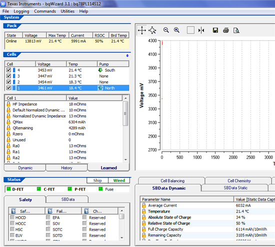
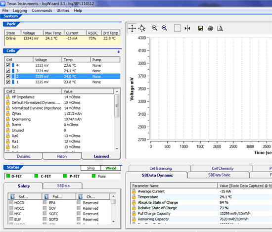
The problem is that after a few cycle the FCC (Full Charge Capacity) drops to a level where the capacity is inconsistent with the real runtime. On some packs capacity goes the other way and is way too high to be consistent. I assume that this new capacity comes from the QMAX of each individual cells.


FCC is too low:
FCC is too high:
 

After a read of the TRM, I understand that QMAX is updated after the pack has been relaxed for long enough at two different qualified points. There is then a lookup of SOC vs OCV and then capacity of the cell is updated. We're using the right chemistry (405 for IFR13-EP1500, this is exactly what we have). I do not understand where this miscalculation comes from.


I would like to correct the event that triggers this miscalculation.


Included in this thread are the .csv dumped from "Save all parameters" from BqWizard. You have access to all the informations available to BqWizard.


7268.All parameters FCC low + FCC high.zip


  • Hi Mathieu,

    Looking at your screen shots, it looks like the Gas Gauge has not been initilized properly.

    Your learned parameters show QMax Learned to vary 6000mA/h for the Low Case and ~ 10,000mA/h for the High case.

    Quick Question:

    Did you run an .aux file generation for your battery pack? The .aux file is a characterization of you particular pack and this information is used in conjunction with the chemID files to initialize the GG.

    The .aux file genertaion is detailed here: http://focus.ti.com/general/docs/lit/getliterature.tsp?literatureNumber=slua505b&fileType=pdf

    Regards,

    Ben

  • Hi Ben,

    I did run the .aux file generation software. BqWizard reported the correct FCC/Qmax at day one for these packs. It's only after time that the FCC drifts and becomes incorrect.

    In other words, during normal usage of the pack (as soon as after 1 cycle), QMax and FCC changes. I need to know what causes this.

  • Benjamin,

    Any update on Mathieu update?

    Alex

  • Hi Mathieu,

    I think at this point, it is important to get the cell chemistry right.

    When the part does an OCV updates, it extracts values from the CemID table. If this table has the wrong values, the part will have the wrong updates from FCC and Qmax.

    During your first cycle, the part uses the values you provided from the aux file. These values are then updated during the idle state of your charge discharge cycle.

    You can try to match the chemID to our libraries by using the bqEasy or send a cell to us here in Dallas for characterization.

    Regards,

    Benjamin


  • Bi Ben,


    ChemID is correct. I am using PHET IP-1500, and that is chemID 405.


    I did run the .aux caracterisation, but I found the Ra value to be very wrong (see previous post http://tinyurl.com/3pllpwo)

    Results from Aux File Utility:


      204 # Ra[ 0]

      236 # Ra[ 1]

      270 # Ra[ 2]

      289 # Ra[ 3]

      263 # Ra[ 4]

      308 # Ra[ 5]

      422 # Ra[ 6]

      578 # Ra[ 7]

      681 # Ra[ 8]

      753 # Ra[ 9]

      831 # Ra[10]

     1044 # Ra[11]

     1108 # Ra[12]

     1316 # Ra[13]

     1463 # Ra[14]


    Instead I did a "manual" caracterisation using a cycler and some maths in Excel, I got the following:


      13 # Ra[ 0]

      13 # Ra[ 1]

      13 # Ra[ 2]

      13 # Ra[ 3]

      13 # Ra[ 4]

      13 # Ra[ 5]

      13 # Ra[ 6]

      13 # Ra[ 7]

      13 # Ra[ 8]

      13 # Ra[ 9]

      13 # Ra[10]

      14 # Ra[11]

      15 # Ra[12]

      16 # Ra[13]

      16 # Ra[14]


    Taken from TRM : 

     Lastly, the new NDI value is compared to the last time NDI was calculated. If there is not an increase in NDI, then the Ra table update is not performed. This filter is in place because cell impedance does not normally decrease with time.

    With the "wrong" values taken from the first caracterisation, values were wrong and stayed at their wrong value forever without ajusting. Now the values are probably lower than reality, so I observed a few packs after a few cycles and the Ra values stabilised at :


      13# Ra[ 0]

      13# Ra[ 1]

      13# Ra[ 2]

      13# Ra[ 3]

      13# Ra[ 4]

      13# Ra[ 5]

      13 # Ra[ 6]

      22# Ra[ 7]

      25# Ra[ 8]

      28# Ra[ 9]

      35# Ra[10]

     46# Ra[11]

     67# Ra[12]

     78# Ra[13]

     79# Ra[14]


    This tells me that the caracterisation done with the aux file utility is complete bull. With these settings, which I believe are far closer to being correct, with a Qmax of ~8900, I usually get a FCC of 8600, which makes sense.


    So, I got the correct ChemID, I got impedances somehow correct on my own. I still have troubles because Qmax goes crazy.


    I tried changing the min OCV slope from the default 2mV/% to a far-too-high 25mV/%, just to disable the function to see if the problem was coming from there. At this point, QMax stopped being wrong and now stays at the same exact value no matter what.


    This tells me my problems lies probably here :


    Q MAX is learned from the change in SOC and Passed Charge between two qualified points in time, P1 and P2. Loosely speaking, the points occur during a time when two consecutive relaxation periods are separated by a period of current flow. The first point occurs during the first relaxation period. Then there is a charge or discharge period that meets a certain minimum change in SOC. Then the second point is during the second relaxation period. The first qualification of P1 and P2 is that the local slope of the OCV table around each point must be greater than the Min OCV Slope parameter. This parameter is typically set to 2mV/% RSOC. Second, P1 is deleted if the time since its acquisition > Stale FCC Timeout. This parameter is typically set to 2880 minutes, or 48 hours. Lastly, the absolute value of the change in SOC since the last learning point must be at least equal to the FCC Learn Qualifier in order for Q MAX learning to take place. This parameter is typically 30% of Design Capacity. There is no temperature restriction on the calculation of Q MAX . If the above conditions are met, estimates of Q MAX updates are calculated as follows: ETC ETC ETC


    If I make the condition to get two qualified points in time impossible, I have no problem. I believe the OCV voltage contained in ChemID is wrong.


    The file 405.chem is binary, is there any way I can verify the OCV tables that the BMS is using for ChemID 405 ? At this point I need to check that the tables are correct with my cells, even if the name of the ChemID is supposedly correct.


    Please give me the OCV tables for chem 405 in clear text.


  • Hi Mathieu and Ben

    Was there ever a resolution to this question? I have made similar observations.

    Mathieu; Did you perform an accurate current calibration on your pack?

    Ben; Are the Ra values that Mathieu obtained though the Aux file utility what you would expect from this pack configuration, or are the values that were manually calculated closer to what you would expect? i.e.: Would you normally expect the Ra numbers for the higher states of charge (Ra[0] - Ra[7]) to be close the the NDI_Initial value?

    Exactly what is the process the aux file uses to calculate the Ra values? The documentation mentions the data collected during the final discharge of the aux file run is used to calculate Ra. I assume the OCV values from the chem file are compared with the cell voltages from the discharge (at the same SOC), and the difference between the two is divided by the discharge current. Is this correct? How are the SOC values between the chem file and the aux file discharge alligned, in order to obtain the two voltages at the exact same SOC, to calculate the resistances?

    Lastly, is the NDI_Gain parameter being set to 32 appropriate for all battery cells, particularly those with low impedances?

    Regards

    Nigel

  • I continued this thread over the phone with TI. It seems, after verification, the ChemID 405 was wrong for the cells it was supposed to work with. TI provided a new ChemID (428) which I need to try in the next days.

    Current calibration was correct on my packs and has been performed.

    The Ra values I were getting were wrong because ChemID was wrong in the first place. However, I did create my own Ra values manually, which worked better even if the ChemID was wrong.

    I'd be interrested to know the answer to Nigel's question regarding NDI_gain ...