This thread has been locked.

If you have a related question, please click the "Ask a related question" button in the top right corner. The newly created question will be automatically linked to this question.

TPS65987D: TPS65987D  I connected a high-speed SSD memory, but the data transfer speed was slow.

Part Number: TPS65987D
Other Parts Discussed in Thread: TUSB1046A-DCI, , TPS65981

Please tell me about the transfer speed of Type-c.
In our system, we connect the TPS65987D and TUSB1046AI in the same way as in "9.3 System Example" in the manual "tusb1046a-dci.pdf".

What we confirmed is that when an SSD (Solid State Drive) is connected directly with Type-c, the speed is very slow, about 35MByte/s, but when connected via a commercially available Type-c hub, the speed is 450MByte/s. .
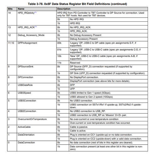
When checking the following terminals on the board with an oscilloscope,
             DP   USB3   HPD    FLIP 
Not connected       “L”   “L”     “L”     “L”
Type-cHub connection   “H”   “H”     “H”    “H or L”
SSD direct connection    “L”   “L”     “L”    “H or L”

I assumed that if I directly connected the SSD, DP (CTL1) and USB3 (CTL0) would be at the "H" level and I expected the speed of USB3.0, but in reality, DP (CTL1) and USB3 (CTL0) were at the "L" level. Therefore, the speed will be USB 2.0.
Our hope is to connect directly to the SSD for high-speed data transfer, but this is currently not possible. Is there any possible reason?

Supplementary information
・SSD specifications are 1T Byte USB3.2 Gen 2×2 (USB 20Gbps).
・When you connect this SSD to a commercially available computer, you can transfer data at high speed.

  • Hi Yamamotoju,

    Due to the holiday, many device experts are currently out of the office. When they return they will look into this and provide a response. Please expect some delay accordingly.

    Thanks,
    Field

  • Hi,

    To me, it sounds like the GPIO events that control the outputs to CTL1 and CTL0 of the TUSB part may not be configured or working correctly. Can you please send me your project file so I can check?

    Best,

    Alex

  • 20230912_ui29_1210.pjt

    Mr. Alex
    We will send you the project file.
    The GPIO assignment of our development board is
    GPIO0 →"Port 0 USB3 Event"
    GPIO2 →"Port 0 DP Mode Selection Event"
    GPIO3 →"Pin Multiplexed to Altemate Function(DP HPD Port 0)"
    GPIO21 →"Por0 Cable Orientation Events"
    Can you think of any other hardware-related factors?

    Yamamoto

  • Hi Yamamoto,

    Do you have access to I2C1 from the PD on your board? If you do, you can try and read register 0x5F Data Status register for details on the connection made with the SSD. 

    Below are my comments on the GPIO setup:

    GPIO0 - Port 0 USB3 Event should trigger on connection of the SSD but it is not in your case. This means the PD may not be recognizing the connection as a USB3 connection. 

    GPIO1 - Port 0 DP Mode Select Event should not trigger on connection of the SSD because the SSD does not support DisplayPort.

    GPIO3 - This is again tied with DisplayPort, which the SSD does not support. This will remain low.

    GPIO21 - Port 0 Cable Orientation will flip with the connection orientation.

    Next step I recommend taking is to gain PD_I2C1 access from your board, so you can read some status registers. Without this information, we are unable to tell what connection is made with the SSD or what is the root cause of the low data rate.

    Best,

    Alex 

  • Mr. Alex

    thank you for your reply.
    Reports the result of 0xF5 register.

    Not connected → 0000000000
    Type-cHub1 → 3305000000
    Type-cHub2 → 3105000000
    SSD direct connection 1 → 0300000000
    SSD direct connection 2 → 0100000000

    *1 is front side 2 is back side

    ・Do I need a software driver?
    ・Is it a hardware problem?

    Yamamoto

  • Hi Yamamoto,

    From our register definition for register 0x5F, the PD does not detect any USB2 or USB3 connection at all when the SSD is attached. In order for the PD to detect the connection type and report the correct connection, the SSD must respond to the PD's Discover Identity request message. Could you please read out register 0x48 so we can see if the SSD responded?

    If you have access to a PD analyzer tool such as TotalPhase or EZ-PD, you could use that to capture the PD messaging for more information. There should not be a hardware issue since the type-C hub you used was working with the PD. There is no software driver for the USB-PD connections, if needed after we find the root cause, we can change the PD configuration.

    Best,

    Alex

  • thank you for your reply.
    Although the confirmation is delayed, I will inform you of the result of the 0x48 register.
    SSD direct connection (byte length 28) All “00”
    →'00000000000000000000000000000000000000000000000000000000
    Type-c Hub (byte length 28)
    → 44E804006C00000000120220A0390000000000000000000000000000
    Were there any factors that could lead to this phenomenon in the project file you sent earlier?
    Is there any problem with setting the other "ADCIN1" terminal to (DIV=0.9) "BP_NoWait"?

  • Hi Yamamoto,

    BP_NoWait is the fastest boot mode from a dead battery scenario. Dead battery is when PD boots from the type-C port without system power. In a normal scenario when PD/system is already powered at connection of the type-C device, dead battery mode does not apply.

    From the result of the register 0x48 read, it looks like the PD did not send Discover Identity message to the far-end connected SSD. Combined with the result of the register 0x5F read you did before, it looks like the SSD is type-C only, so we would not do the same discover identity sequence that we do for PD. That being said, there should still be a USB3 type-C connection.

    Do you have a way of capturing the CC signals using a scope or analyzer? Please try to capture the CC signals and also read out the 0x69 Type-C State register. This will help us see the CC voltage levels and see if a connection was made properly. Additionally, if you want to send me the schematic for your board, I can take a look and check the connections as well.

    Best,

    Alex

  • Mr. Alex
    thank you for your reply.
    We are currently preparing to submit the circuit diagram, but we need to confirm it first.
    I may be misunderstanding
    Table 3-12. 0x28 Port Configuration Register Bit Field Definitions (continued) Bytes 1-2: Port Configuration
     14:13 USB3rate(2) {(2) Initialized by Application Customization.}
     It seems that you can set USB3 with , but is it possible to adjust the speed by writing arbitrary settings to this register?
     00b USB3 not supported
     01b USB3 Gen1 signaling rate supported
     10b USB3 Gen2 signaling rate supported
     11b Reserve
    Yamamoto
  • Hi Yamamoto,

    The USB3.0/3.1 rate field of 0x28 Port Configuration register is used to set the maximum USB3 data rate for PD connections. If you select USB3 Gen2 for example, that will be the maximum speed of a USB3 connection on the port, but does not necessarily set the actual USB3 connection speed. The PD will determine the USB3 connection speed to report based on a combination of the USB3 rate field and the cable VDO response (PD message). So technically it is possible as long as the max USB3 speed set by the PD is not higher than the max USB3 speed supported by the SSD or other device.

    • If USB3 Rate in 0x28 Port Config = USB3 Gen2 and max USB3 speed supported by SSD = USB3 Gen1
      • USB3 speed of connection = USB3 Gen1
    • If USB3 Rate in 0x28 Port Config = USB3 Gen2 and max USB3 speed supported by SSD = USB3 Gen2
      • USB3 speed of connection = USB3 Gen2
    • If USB3 Rate in 0x28 Port Config = USB3 Gen1 and max USB3 speed supported by SSD = USB3 Gen2
      • USB3 speed of connection = USB3 Gen2

    In our debug, the USB3 SSD you tested with did not negotiate a PD connection with the TPS65987D, so the connection is limited to low non-USB3 speed. The issue is with establishing the PD connection with the SSD. Once this occurs properly at connection, USB3 speed should be established normally.

    It is difficult to debug this without a PD analyzer. I recommend obtaining one, it will also help debug in the future, if it is needed. The next step I recommend is to read out register 0x69 when the connection with the SSD is made, for information on the CC pins and type-C state.

    Best,

    Alex

  • Mr. Alex
    thank you for your reply.
    I would like to confirm the contents of your comment.
    Also, regarding "if you want to send me the schematic for your board, I can take a look and check the connections as well.", we will send you a document with an excerpt of the circuit diagram, so please check it.
    The materials we will send
    (1) Circuit diagram around TPS65987D
    (2) Circuit diagram around TUSB1046AI
    Our system intentionally does not allow PD (Power Delivery) to function.
    Also, power is already being supplied to our system when a Type-C device is connected, so what is the appropriate setting for the "ADCIN1" terminal?

  • Hi Yamamoto,

    The schematics look ok. I do not suspect this is a hardware issue.

    I did check again on your project and there is just one setting that could be impacting the USB2/USB3 detection at the port. I toggled the USBCapable field of the 0x32 TX Source capabilities register PDO1 to true. Please test this configuration and see if anything changes.

    20240421_ui29_1210.pjt

    Since your system does not boot from the type-C port in dead battery condition, you do not need to worry about the ADCIN dead battery configurations. The ADCIN2 pins will only be used to set the I2C address like below. The ADCIN1 pin is a "don't care" from the PD point of view unless booting with no system power.

    Best,

    Alex

  • Mr. Alex
    > Switched the USBCapable field of PDO1 to true. Test this configuration and see if anything changes.
    ⇒After checking, the desired behavior was achieved and the issue was resolved.
    thank you very much.
    To verify this, we confirmed the following.
    (1).Results of transfer speed measurement application software
    Changed from 35MByte/s to 280MByte/s.
    (2).Checking the USB3 (CTL0) signal on the board
    When I checked the voltage with an oscilloscope, it changed from "L" to "H" level.
    (3).0x5F (Data Status) register read result
    The first byte changed from “0” to “3”.
    SSD direct connection 1: 0300000000 → 3300000000
    SSD direct connection 2: 0100000000 → 3100000000
    *1 is front side 2 is back side
    I have achieved my goal, but there are some things I would like to review for the future.
    (1).Do you have any explanatory materials regarding the "PDO1 USBCapable field settings" that you pointed out?
    (2).We made various settings using "TPS65981_2_7_8 Application Customization Tool", but there are many combinations of settings, so is there any explanatory material for all of these settings?
    Yamamoto