This thread has been locked.

If you have a related question, please click the "Ask a related question" button in the top right corner. The newly created question will be automatically linked to this question.

TPS25750: General explanation of how is work

Part Number: TPS25750


Dear, I am not really understanding mainly how it works. In fact, I have I2C communication between my host and the device but I can't write PDO registers (always read them return 0).

I read the mode and it return "PTCH" and I suppose that it is why it not accept to write registers.

It seems that the unic way is to send Patch Bundle Burst for set the device using 4CC command.

I really don't have clear the datas to sent in this patch bundle. Do you have any document for discribe it?

Any explanation of general process for use the device will be welcome.

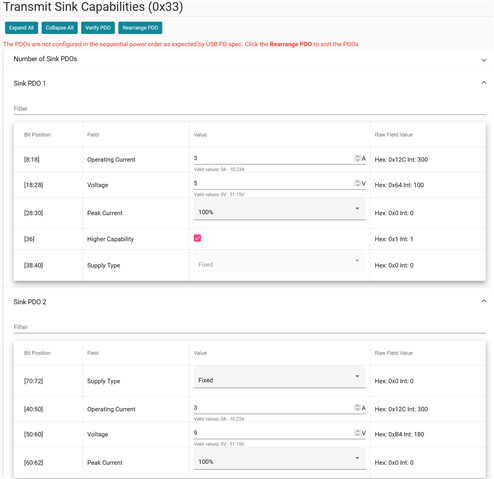
Another details, can you confirm that the voltage setting registers are 50mV/bit and current setting 10mA/bit?

Thanks in advance and Best regards

Thierry Q.

  • Hi Thierry,

    Due to the holiday, many device experts are currently out of the office. When they return they will look into this and provide a response. Please expect some delay accordingly.

    Thanks,
    Field

  • Hi Thierry,

    I have attached documentation on how to use PBM commands.

    Could you confirm which registers you're referring to?

    Kind regards,

    Conner Gillette0880.PBMx.pptx

  • Hi Conner,

    Thanks for the document.

    The charflow say "execute FOR loop to write all EEPROM bytes". I am not using EEPROM so which data I must send with host cpu? Is it a binary dump build with the configurator tool?

    The registers that I was refering are:

    "TX_SINK_CAPS (0x33)" and TX_SOURCE_CAPS (0x32)". I write some values but read return "0". Read "MODE" return PTCH value.

    On each one you may specify the PDOs values. Here, the datasheet don't specify the current and voltage resolution. I deduce them from USB-IF document.

    BR

    Thierry Q.

  • Hi again,

    I just saw a similar thread regard the TPS25750 use without EEPROM and it seems need to laod the Low Region or Full Flash data build with the configurator tool.

    I am disapointed because load more than 15kB of data each time I start the system will take time and increase malfunctions risk.

    Please confirm it asap this topic.

    Best regards

    Thierry Q.

  • The low region binary is what needs to be used to load the configuration for PBM using an EC.

    Yes, I can confirm that the PDO registers are 50mV/bit and current setting 10mA/bit.

    Kind regards,

    Conner Gillette

  • Hi,

    No answer since my last post.

    I am doing the patch bundle load following the datasheet procedure.

    - Wait for bit ReadyForPatch=1 on EVENT1

    - Send the PBMs commande and wait for ack

    - Send the bundle burst

    At this step, I have a doubt. Should I sent all bytes using the DATA1 or sending I2C address followed by all bytes?

    Is the I2C address for bundle burst must be a different one than the default one?

    BR

    Thierry

  • Oups, the page was not up to date.

    Thanks for confirmation.

    I am trying to send this patch bundle.

  • To answer your question, from the TRM:

    "The host may send the entire Patch Bundle in a single I2C transaction, or it may break it into multiple transactions. The PD controller increments the pointer into its patch memory space with each byte received on the Patch Slave address that was configured as part of the 'PBMs' 4CC Task."

    This is referring to the address used in bits 6:0 in Input Data X in the PBMs command.

    Kind regards,

    Conner Gillette

  • Thank Conner,

    I found the failure, was the I2C address not shifted setting PBMs command.

    Now, I pass all flowchar steps less last one.

    PBMc DATA1 give 0 so, no error.

    Reading the INT_EVENT1 status,  flag "Patch Loaded" stay =0 and ReadyForPatch=1 (Byte11=0x02)

    Any Idea or register to read for check errors?

    Thierry

  • Yes, I would check Output DataX for PBMc, bits 215:16. (Table 3-10 in the Technical Reference Manual)

    Let me know if any of the outputs for these statuses appear wrong.

    Kind regards,

    Conner Gillette

  • Hi Connor,

    I found another failure on my code.

    Patch is loaded successfuly now and device switch to APP mode

    Reading capabilities return 0xF8 (DRP, PD suported,...)

    However, I send PDOs Sink and Source profile using TX_SOURCE_CAPS and TX_SINK_CAPS but when I readback, result is 0x00 on whole Sink and Source PDO registers.

    Do you have any configuration example for check if I am doing something wrong?

    PDOs data will be these ones. I need only source 5V 1A (0,5A for first test) and sink 20V with several current capabilities.

    BR

    Thierry

  • Hi again,

    I PDOs setting still not wrote.

    Looking for more information on the forum, I found some thread speaking about PDO settings.

    I discover that the software tool can also make presetting of these PDOs with advanced menu however, I have an error message include with default setting.

    In which order PDOs must be set? Increasing or decreasing? I don't reach to find info on the web.

    Any help will be welcome.

  • At the end, I think I was wrong thinking about RX_SINK or RX_SOURCE register. 

    We will save time if you have any negociation flowchart document for explain how to iniciate the processus when a cable is connected.

    I plug a 100W charger and it only give 5V on the demo board (MikroE). I suppose it is the default status.

    Then, could be I have to send some commande for start the negociattion or it should be do it itself?

    BR

    Thierry

  • Hi Thierry,

    Let me know if this document helps to answer your questions. It goes over USB Power Negotiations in depth.

    Kind regards,

    Conner Gillette

  • Hi Conner,

    Yes it help. I mainly have to learn USB PD concept before for better understand how to use the chips. For example, where use fixed or variable voltage PDOs.

    In fact, I was reading "RX_SINK" and "RX_SOURCE" for check "TX_SINK" and "TX_SOURCE". "RX" are for read PDOs from connected device.

    So, reading the good ("TX") register I detect an error loading the PDOs data. I fix it and now is working and reach 20V as expected.

    Also, I am able to read the contract result and so, can manage the charge current depending of power supply capability.

    Still to try source mode but I am not afraid because it should work.

    To resume, I think that in the datasheet  was missing an small introduction  showing a basic USB PD transaction concept and also a small picture to explain quickly that the TPS need a code load using the web tool (where I detect some bugs to fix). 

    Thank you for your help.

    BR

    Thierry

  • That's good to hear, Thierry.

    Thank you for the constructive feedback, I will relay it to the team.

    Kind regards,

    Conner Gillette