This thread has been locked.

If you have a related question, please click the "Ask a related question" button in the top right corner. The newly created question will be automatically linked to this question.

UCD3138ALLCEVM150: Calculations for sensing of primary current signal (IPS) and calibration in firmware for the same.

Part Number: UCD3138ALLCEVM150
Other Parts Discussed in Thread: UCD3138A, , PMP, UCD3138128A, UCD3138PFCEVM-026, UCD3138, PMP40586, PMP20978, TIDA-00512

Hi,

I am trying to scale LLC power converter rating using UCD3138ALLCEVM150 as a reference.

I have also understood the scaling for the signals VIN_MON, IO_SENSE and VOSADC12 using the following thread: Link

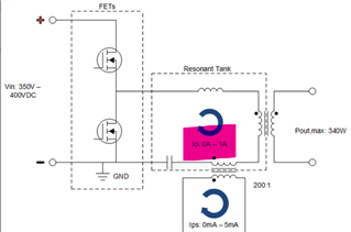
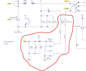
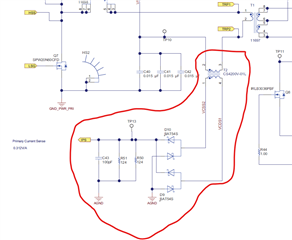
Can anyone please explain regarding the calculation of IPS signal from primary current CT. (as shown in the Fig)
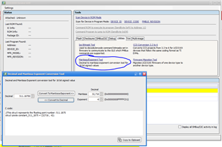
Also, please explain regarding the calibration in the firmware. How do I calculate the mantissa and exponent for the related variable IIN in the following code in system_defines.h:

#define ADC12_IIN_SCALER_MANTISSA   (32716)
#define ADC12_IIN_SCALER_EXPONENT   (-6)

  • Hello,

    We are on holiday for Good Friday today and I will give a response next week.

    Regards,

    Jonathan Wong

  • Hello PP N,

    Please see the diagram below for a system explanation.

    The IPS current sense network allows the UCD3138A to detect a voltage across a current sense resistor that is proportional to the current in the resonant tank. Let's divide the calculation into various steps.

    Step 1: Calculate Initial Parameters in LLC

    The input voltage is set as 350VDC - 400VDC. The output power is 340W. So, using P = IV, we can estimate that the current in the resonant tank will vary from 0A - 1A (this is an estimate that will simplify the calculations). The current sense transformer used in the schematic is CS4200V-01L. Looking at the datasheet, the turns ratio is 200:1. 

    Step 2: Calculate Voltage Across Current Sense

    Since the turns ratio is 200:1, then if the current in the resonant tank is 1A, then the current in the IPS network will be 5mA. So, we can estimate that the current in the IPS network will vary from 0mA - 5mA. This current then goes across two parallel 124Ω resistors (62Ω equivalent). Using V = IR, the voltage across the current sense resistors will vary from 0V - 0.31V. The UCD3138A ADC04 uses a Hi-Z measurement to measure the voltage across the current sense resistors.

    Step 3: Scale ADC Voltage to ADC Count

    The ADC converts a max 2.5V equal to an ADC count of 4096. Using this scale, we can calculate that 0.31V is equal to an ADC count of 508. Using the mantissa tool in the UCD Device GUI, a Mantissa = 32,716 and Exponent = -6 equals a decimal of 511.18750, which is close to our max calculated current. Thus, we see that the IPS network can sense up to around 1A in the resonant tank.

    Please let me know if this answers your question and if you have any further questions.

    Regards,

    Jonathan Wong

  • Hi Jonathan,
    Thank you for the detailed description.

    I just need a bit more clarification regarding Ip (= 0-1A) i.e., whether it is the peak value or the RMS value of resonant current?


    Regards,

    Pratik

  • Hello Pratik,

    That should be the RMS value. 

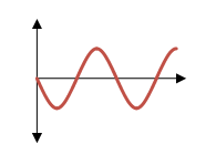
    Correction: The waveform shows a sine wave with no offset in the resonant LLC tank. This is only for a Full Bridge LLC. A Half Bridge LLC will be a sine wave with a peak of Vin and an offset of Vin/2. 


    Regards,

    Jonathan Wong

  • Hello Jonathan,

    I request you please check once. I have done the calculations again and it turned out that the peak value of Ip is 1A. It may not be the RMS value.

  • Hello Pratik,

    I think it should be the RMS value. Going into the 62Ω current sense resistor, the current is already rectified. So the ADC must see DC 0mA - 5mA.

    Also, if we have an input voltage of 340V and input power of 340W, then the input DC current must be 1A. This 1A DC current is then converted to a square wave and then a sine wave. For the power to be the same, the current inside the resonant tank must be the RMS value. If 1A was the peak value, then the power level will be lower since the RMS value would be 1A/√2, or about 0.707Arms. 

    Regards,

    Jonathan Wong

  • Hello Jonathan,

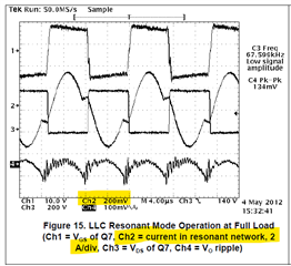
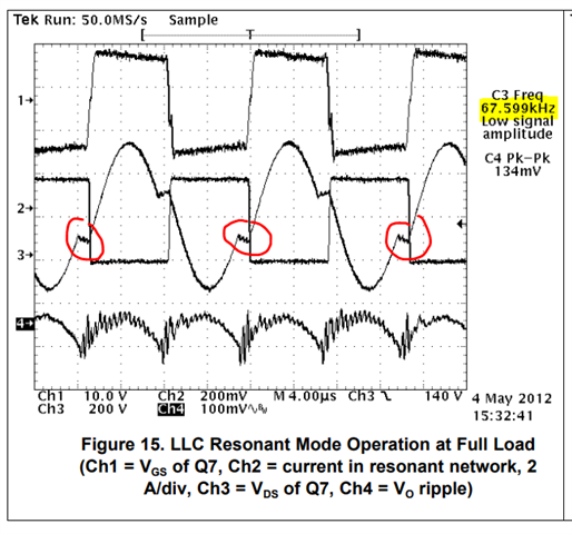
    As per the test results in the UCD3138ALLCEVM150 user guide (Page 15) and attached below, at rated power when Vdc = 380V and switching frequency = 67.59 kHz, the peak resonant current is approximately 3.2A, so corresponding RMS value must be 1.8Arms (which is more than expected value).

    However, as per your suggestion, it is would be 1Arms at the rated load.

    So, I request you to please probe the ADC signal IPS on the UCD3138ALLCEVM150.

    I would be grateful if you could share the desired waveform.

    Regards,

    Pratik.

  • Hello Pratik,

    How did you get an RMS value of 1.8Arms? If the Ipeak = 3.2A, then Irms = 3.2/√2 = 2.26Arms.

    Regardless, you are right that the current is higher than my calculation. I will take some measurements and get back to you by the end of the week. Thank you for your patience.

    Regards,

    Jonathan Wong

  • Hello Jonathan,

    Yes, the rms value should be 2.26Arms. It seems to be a typing error on my side.

    Further, thanks for consideration of my request to probe the IPS current sense signal.

    I will await the results of your findings.

    Regards,

    Pratik

  • Hello Pratik,

    Apologies for the delay, I needed to get a new UCD3138A control card and I just received it. I will take measurements today and let you know the results by tomorrow.

    Regards,

    Jonathan Wong

  • Hello Jonathan,

    I am thankful for your concern. I will await the results of your findings.

    Thanks and Regards,

    Pratik

  • Hello Pratik,

    You are right that the current in the resonant tank will be higher than 1A. Finding the current in the resonant tank is not straight forward and I made a mistake saying that the max peak current in the resonant tank will be 1A. While the input current will be max DC 1A, the current in the resonant tank is harder to predict. 

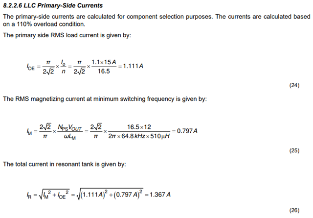
    The current in the resonant tank will be the current across the magnetizing inductor and the reflected current from the secondary-side current. Page 58 of the UCC25640x LLC controller datasheet (https://www.ti.com/lit/ds/symlink/ucc256403.pdf) has good equations that allow you to estimate the current in the resonant tank. Variable explanation: "IO" is the output DC current, "n" is the turns ratio, "IOE" is the reflected current from secondary-side, "Nps" is the primary side turns, "Vout" is the output voltage, "Lm" is the magnetizing inductance, "IM" is the current across the magnetizing inductor, "IR" is the total current in the resonant tank. 

    In an LLC, the peak current in the resonant tank will be lowest when the resonant tank is operating at resonant frequency. In Figure 15 from the UCD LLC EVM User's Guide, you can tell that the measurement was not taken at resonant frequency. You can see that there is distortion in the sinusoidal current at the zero crossings. At resonant frequency operation, the current will be a perfect sinusoidal waveform and the peak current will be much lower. You can calculate the resonant frequency using Equation 1 on page 4 from Design and Optimization of a High-Performance LLC Converter (https://www.ti.com/seclit/ml/slup306/slup306.pdf).  

    The calculations and the diagram that I made in the initial post is true. However, the mistake is the assumption of what the (32716, -6) value is used for. If we look in the UCD LLC-HB firmware, the value is only used in the configure_warnings_levels() function. Thus, 1A is not a hard measurement limit for the resonant tank. I assume this means that when the current in the resonant tank goes above 1A, then the warning will be triggered. However, this does NOT mean that the current in the resonant tank cannot exceed 1A and that the UCD cannot measure current above 1A. As we saw in the scaling, 1A corresponds to an ADC count of 508. Thus, a max ADC count of 4096 should correspond to ~8A measurement. So, the UCD should be capable of detecting up to an 8A peak current in the resonant tank. It will be up to you if you want to change the warning levels.

    Please let me know if you have any further questions.

    Regards,

    Jonathan Wong

  • Hello Jonathan,

    I thank you and really appreciate the efforts you have put in towards the resolution of my query. It clarifies the calculation of resonant current to me.

    Now, I only have a couple of things to be clarified:

    1) Does the sense signal IPS not participate the the closed loop control and is only restricted to the warning levels?

    2) Also, the firmware code is a bit difficult to be understood. If possible, can you please share some related documentation regarding the firmware (something that covers the ADC scaling/ calibration of sensed parameters, control block diagram and role of each sensed parameter.)

    Awaiting your response. Kindly let me know.

    Best Regards,

    Pratik

  • Hello Pratik,

    Happy to help with your question. Thank you for using TI's UCD devices. To answer your questions:

    Question 1

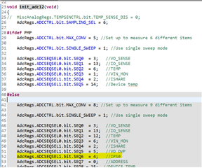
    A good way to track what the ADC signal is used for is to start by looking at where the ADCs are declared. If you look in the main(), then the ADCs are declared in init_adc12(). In init_adc12(), we see that ADC04, which is the IPS, is not used in the PMP configuration. So, it looks like the signal is not even used for the UCD LLC EVM w/ the UCD3138A control card.


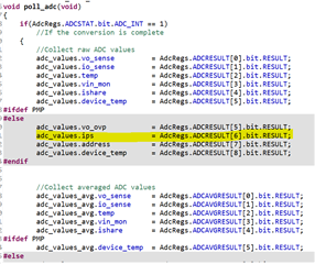
    Another good way to track how the ADC used is by looking at the polling. Most UCD code will have a function called poll_adc() (usually in standard_interrupt.c). Here, we can also see that the IPS is also not used in the PMP configuration. If you were to use other build configurations with other UCD controllers (Ex. the UCD3138128A), then the IPS would be used.

    Question 2

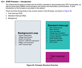
    Yes, the code is not the most readable. I do not believe we have a good in-depth walkthrough of the LLC-HB firmware. We do have good documentation of the PFC EVM firmware. The PFC firmware is much more complicated than the LLC-HB firmware. So, if you can understand the PFC firmware, then understanding the LLC-HB firmware will be straight-forward as long as you know the LLC design fundamentals. The EVM User's Guide has a good firmware overview in section 12.4 on page 37 (EVM Firmware - Introduction). Many of the architecture ideas can be transferred to the LLC.

    PFC Firmware Documentation:

    It may also be helpful to look at other Half Bridge LLC reference designs. We have 3. The LLC-HB EVM used to be a reference design before becoming an EVM so there is also a reference design test report available.

    Please let me know if you have further questions.

    Regards,

    Jonathan Wong

  • Hello Pratik,

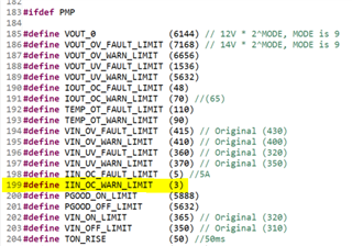
    Slight correction, if you look at the configure_warning_levels(), you will see that the adc12_iin_scaler is used in line 120 to configure the iin_oc_warn_limit. The iin_oc_warn_limit is initialized in pmbus_topology.h line 199 as (3). This means that the actual Iin warning would be when the resonant tank is 3A. This IIN_OC_WARN_LIMIT is the value that can be changed in the Fusion Studio GUI to be whatever limit you want. 

    Regards,

    Jonathan Wong

  • Thank you Jonathan.
    I am getting it now.