Other Parts Discussed in Thread: BQ24610, , EV2400, BQ25606, BQSTUDIO, GPCCEDV, BQ27320, BQ24610EVM
Dear TI team,
I am currently working on a project that needs a Battery Charger and a Fuel Gauge for accurate Battery SoC tracking.
For the Charger I have chosen, BQ24610 and for the fuel gauge, I have chosen BQ27220.
Following are the Input and Output specs of the system,
Input: DC charger with 5V, 5A capabilities.
Battery Specs: 1S2P, 3.6V Nominal Voltage(4.2V Max), Li-Ion Pack(10,000mAh). The battery charge current needed is 4.5A.
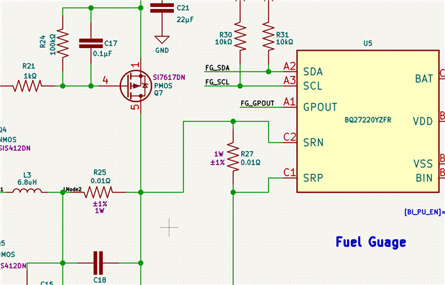
I have made the following attached schematic based on reading the datasheets of both ICs. Can someone from both the charger and fuel gauge teams confirm if the schematic is OK before I proceed to the PCB layout section?
I also had the following questions while designing.
- For BQ27220, what is the nominal voltage for SDA SCL lines for BQ27220? Can I interface(read/write) it with a 3V3 voltage compatible microcontroller without any voltage translations?
- Is the position of the sense resistor for BQ27220 correctly placed in the BQ24610 charger path?
- Can someone explain, the use of R3 and C3 mentioned in the schematic, placed between the 2 PMOSs in BQ24610?
- In the fast charge mode of the battery when set at a charge current of 4.5A and the DC input limit set at 5A, Can I assume that the rest of the 500mA will be available at the output of the BQ27220(Vsys node) while the charge is in progress?
It will be great if someone can help with the above. Thanking you in advance.


