This thread has been locked.

If you have a related question, please click the "Ask a related question" button in the top right corner. The newly created question will be automatically linked to this question.

TPS23731: Is TPS23731 the best device for LTC4278 replacement?

Part Number: TPS23731
Other Parts Discussed in Thread: TPS23755, TPS23758, TPS23753, PMP22806, TPS23758EVM-080, TPS23756

Hello guys,

One of my customers is looking for TI device which can replace LTC4278IDKD.

I found TPS23731RMTR for that.
Is TPS23731 the best device for LTC4278 replacement?
Or is there any other TI device?

Your reply would be much appreciated.

Best regards,
Kazuya.

  • Hi Kazuya,

    TPS23731 is the best device to replace LTC4278. This device is an IEEE802.3bt standard device, compared with the LTC4278 which is older standadrd IEEE802.3at standard. Thanks!

    Regards,

    Brandon

  • Hi Brandon,

    Thank you very much for your reply.

    Could I ask you additional questions as the below?

    Q1. 
    Can TPS23731 be set for IEEE 802.3af class2 or class 3?

    Q2.
    If Q1 answer is yes, could you please tell me how to set?

    Thank you again and best regards,
    Kazuya.

  • Hi Kazuya,

    Q1: Yes it can! All IEEE802.3bt devices are backwards compliant. Therefore, TPS23731 can be Type 1 or Type 2 as well. 

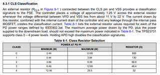
    Q2: The class level is controlled by an external classification resistor which is measured by the PSE and the current sank during classification. 

    Regards,

    Brandon

  • Hi Brandon,

    Thank you very much for your reply.

    The reply is very helpful for the customer and me.
    Could I ask you an additional questions about TPS23731 and TPS23755 as the follows.
    If I should ask these on a new thread, could you please let me know?

    Q1. 
    They considering using TPS23755 too because they want to reduce system cost. 
    The customer needs to support only IEEE802.3af Class2/3 at their new products.
    In the case, can TPS23755 be used?

    Q2.
    They want to apply the power to their products from either PoE line (48V) or DC adapter(10V~30V).
    Also they want to give priority to the DC adapter when both power source are connected.
    Is it possible to implement this function using TPS23731 and TPS23755?

    Q3.
    If Q2 answer is no, do you have any recommended device or circuit to implement the function? 

    Thank you again and best regards,
    Kazuya.

  • Hi Kazuya,

    Of course, happy to help. Please see my responses below! 

    Q1: If they only need IEEE802.3af standard power levels, then yes TPS23755/8 are best devices here. The main different between the two are what output voltage they are optimized for. Please see Q2 for a more in depth comparison between these two devices. 

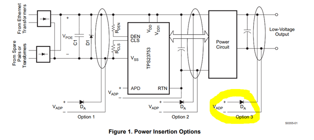
    Q2: TPS23731 and TPS23755/8 support this. For TPS23755 and TPS23758 the main difference is output voltage. For applications where output voltage >=12V I would recommend TPS23755 and TPS23758 for <12V outputs. Also, TPS23755 supports secondary side auxillary power which basically steps down the output of the DCDC to allow for a smooth transition from PoE power to AUX power (DC adapter). On the contrary, TPS23758 allows for primary side AUX power which disables the internal MOSFET but keeps the output of the DCDC enabled with AUX input. I am attaching a APP note that describes the different types of AUX input here. Let me know if any questions!

    Q3: N/A see above!

    Regards,

    Brandon

  • Hi Brandon,

    Thank you very much for your reply.

    The APP note you attached is very helpful for the customer and me.
    Could I ask you a question about the APP note?

    Q.
    3.3 I think option 2 in the APP note would be the best to implement the function for DC adapter prioritization.
    But I couldn't find the pin of TPS23755 which has same function as the APD pin of TPS23753.
    Can this option 2 not be applied to TPS23755?

    Thank you again  and best regards,
    Kazuya. 

  • Hi Kazuya,

    TPS23755 has secondary side adapter input, not primary side adapter input. Therefore, if you wish to use OR'ing option 2 I would recommend TPS23758 which has primary side OR'ing functionality. Note, when using TPS23758 you will need secondary side sync-FET.

    Regards,

    Brandon

  • Hi Brandon,

    Thank you very much for your supports a lot.

    The customer has the following questions.
    Could you please give me your reply?

    Q1.
    We can see the following sentence on page 29 of TPS23755.
    "Many of the basic ORing configurations and much of the discussion contained in the application
    note Advanced Adapter ORing Solutions using the TPS23753, (SLVA306), apply to the TPS23755."
    But I think Figure 8 on page 10 of the application note, SLVA306 can not be applied because TPS23755 doesn't have APD pin.
    Is my thought correct?

    Q2.
    You said that you recommend TPS23758 which has primary side OR'ing functionality. 
    But we want to generate just 12V at secondly side (Vo).  
    You said that I recommended to use TPS23758 in case of <12V output.
    Also the following E2E URL says that TPS23758 should be used for 5V/3.3V output.
    https://e2e.ti.com/support/power-management-group/power-management/f/power-management-forum/805810/faq-tps23758-difference-between-tps23758-and-tps23755

    Is this thread correct?
    Is it difficult to generate just 12V with TPS23758?
    If this answer is yes, could you tell me the reason?

    Thank you again and best regards,
    Kazuya.

  • Hi Kazuya,

    Please see my responses to your questions. Thank you!

    Q1: Your understanding is correct.

    Q2: TPS23755 is optimzed for diode rectification due to CP pin structure. For high Vout & low Iout applications in at/af (12 V or higher) diode rectification is more common since it is cheaper solution.
    The sync FET (TPS23758 is optimized on) is normally used for secondary side has high current. The diode forward drop is ~0.7V. For example, 5V/2.4A output has 0.7 x 2.4 = 1.68W loss; 12V/1A output has 0.7 x 1 = 0.7W loss.

    Regards,

    Brandon

  • Hi Brandon.

    Thank you very much for your reply.

    Do you means that the advantage of synchronous rectification with 12V output is small though TPS23758 can generate 12V on the secondary side?

    Thank you again and best regards,
    Kazuya.

  • Hi Kazuya,

    The sync FET rectification (TPS23758) is better optimized for lower output voltages since you have less power loss compared to diode rectification (TPS23755) where your forward voltage drop is 0.7V. Therfore, in the case of lower voltage output, with diode rectification you will have a higher current combined with the forward voltage drop leading to more power loss. This is why we recommend TPS23758 for lower output voltage as the FET has better efficiency but is typically more expensive. 

    In customers case here, since they wish to use primary side adapter OR'ing they need to use TPS23755 since the TPS23758 supports secondary side adapter OR'ing. 

    Both solutions can output the same voltage...3.3V, 5V, 12V but it essentially comes down to efficiency and feature set (adapter OR'ing selection).

    Regards,

    Brandon

  • Hi Brandon,

    Thank you a lot for your many supports.

    Could I ask additional questions as the below?
    Q1.
    You said "In customers case here, since they wish to use primary side adapter OR'ing they need to use TPS23755 since the TPS23758 supports secondary side adapter OR'ing. "
    I think this is not correct and the correct sentence is the below.
    "In customers case here, since they wish to use primary side adapter OR'ing they need to use TPS23758 since the TPS23755 supports secondary side adapter OR'ing. ". Is my thought correct?

    Q2.
    The followings are their current requirements.
    Input voltage: 37V~57V(PoE) or DC10.5V~30V(Adapter)
    (If voltage is supplied from both, give priority to the voltage of the adapter.)
    Output voltage: 12V
    Output current: 0.5A
    They are considering using TPS23731 too for the requirements.
    In this case, they think TPS23731 needs to be have buck-boost function and think PMP22806 could be used for the requirements.
    https://www.ti.com/tool/ja-jp/PMP22806
    Is their thought correct?
    and is there any other reference design or any design tool for designing for the requirements?

    Thank you again and best regards,
    Kazuya.  

  • Hi Kazuya,

    Q1. Apologize for the typo, yes you are correct, TPS23758 is needed for primary side adapter OR'ing.

    Q2. PMP22806 is a reference design for isolated flyback. Do they need an isolated design? If so, buck converter would not be the way to go. Can you provide their full requirement and I will check to see if we have a reference design that matches their requirements? We have a repository of reference designs that can be leveraged to help complete the design and used for evaluation. TPS23731 can also be used for primary side adapter input!

    Regards,

    Brandon

  • Hi Brandon,

    Thank you very much for your kind words.

    Yes. They need isolation for the circuit.

    They are considering using TPS23731 or TPS23758 for their products.

    Their requirements are below.
    Input voltage: 37V~57V(PoE) or DC10.5V~30V(Adapter)
    Output voltage: 12V
    Output current: 0.5A
    If voltage is supplied from both, give priority to the voltage of the adapter.
    Back-boost function is needed when DC adapter is connected because the adapter voltage range is DC10.5V~30V.
    IEEE802.3af class 3 must be implemented.


    Could you please tell me any reference design which can suit to their requirement?
    If you need any other condition to look for TI reference design, please let me know?

    Thank you again and best regards,
    Kazuya.

  • Hi Kazuya,

    Thanks for your information. 

    It is recommended to boost DC10.5V~30V(Adapter) to 36 V - 57 V first. TPS23758EVM-080 (www.ti.com/.../slvubo2b.pdf) is a 5-V output reference design with 48-V adapter input that you can start with. You can modify it as below to make it 12 V / 0.5 A output.

    The transformer can be alternative with others with 12-V Vout and 1:1 AUX:SEC turns ratio. 

    Best regards,

    Diang

  • Hello Diang,

    Thank you very much for your reply.

    The reply is very helpful for the customer and me.
    I attached excel file for confirming which point must be modified.
    Could you please take a look and check it if it is correct?
    And if you find any wrong point, could you please tell me it?

    Also please tell me D1a and D2a spec?

    Thank you again and best regards,
    Kazuya.

    AttchedFile041724a.xlsx

  • Hi Kazuya,

    Thanks for your updates. I will get back to you by Friday.

    Best regards,

    Diang

  • Hi Diang,

    Thank you very much for your reply.

    I'm looking forward to receiving your reply.

    Thank you again and best regards,
    Kazuya.

  • Hi Kazuya,

    You are welcome and thanks for your patience! 

    Best regards,

    Diang

  • Hi Kazuya,

    Thanks for your patience! 

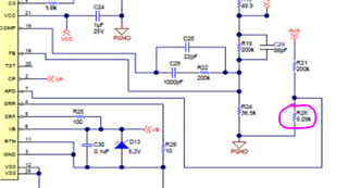
    Recommend to increase R26 from 9.09k to ~13k. Threshold of APD is ~1.5 V so a 30V adapter needs a higher resistor divider ratio. Other parts look good to me.

    Best regards,

    Diang

  • Hi Diang,

    Thank you very much for your checking.

    I understood. I will tell the customer to change R26 to ~13kohm.
    Could I ask you the following questions additionally?

    Q1. What should "If" of D1a in my excel file be chosen?

    Q2.  What should "Vr" and "If" of D2a in my excel file be chosen?

    Thank you again and best regards,
    Kazuya.

  • Hi Kazuya,

    You are welcome!

    - D1a can be 100V Vr 100mA If rated, either PN or Schottky;

    - D2a is better with low Vf for better efficiency. 60V Vr, 3-5A If should work.

    Best regards,

    Diang


  • Hi Diang,

    Thank you very much for your reply.

    Can I ask you one more question?

    Is there TPS23731 reference design which suit to their requirements?

    [Their requirements, these are same as previous]
    Input voltage: 37V~57V(PoE) or DC10.5V~30V(Adapter)
    Output voltage: 12V
    Output current: 0.5A
    If voltage is supplied from both, give priority to the voltage of the adapter.
    Back-boost function is needed when DC adapter is connected because the adapter voltage range is DC10.5V~30V.
    IEEE802.3af class 3 must be implemented.

    Thank you again and best regards,
    Kazuya. 

  • Hi Diang,

    Thank you very much for your strong supports.

    I told your recommendation that adapter input voltage should be boosted to 37~57V.
    But it is difficult to adopt it for them because it causes cost up and solution board size increasing.

    Is there any solution without the boost converter for the adapter voltage?

    And they could consider to adopt a non isolation solution if solution cost and size is small.
    If you have any idea for non isolation solution, could you please  give me it?

    Thank you again and best regards,
    Kazuya.
       

  • Hi Kazuya,

    Thanks for your updates. 

    1. In most of cases, 12-V isolated adapter can be oringed on the secondary side. Checking https://www.ti.com/lit/an/slva306a/slva306a.pdf for more details. 

    2. About non-isolation design: most of PoE PD design relies on the isolated DC/DC to be compliance with the 802.3 standard. Please let us know if you confirm that you need a non-isolated design.    

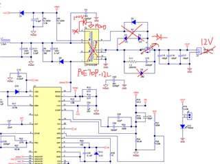
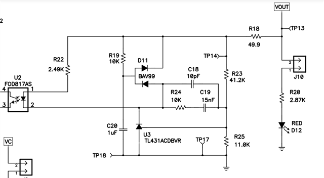
    3. TPS23755 can be configured as a low side switching buck like attached schematic. While the GND of input and GND of output have a voltage difference. Is it ok to you? If you want a input&output same ground, you can refer www.ti.com/.../PMP11257

    2642.PSIL048E1(001)_Sch.PDF

    Best regards,

    Diang

    3. 

  • Diang,

    Thank you very much for your strong supports and I'm sorry to be late my response because I took a vacation.

    About 1,
    It is difficult to use option 3 for them because their adaptor voltage range is wide(10~30V)
    and a buck-boost converter will be needed for 12V/0.5A output.
    They don't want to add any DCDC converter to reduce cost.

    About 2,
    I confirmed them whether isolation is mandatory or not. They said isolation is not mandatory but they want to consider isolation circuit at first.
    Is there any other isolated circuit which suit to their requirement?


    About3, I will tell them this application and I will confirm whether the different GND level is OK for them or not.

    Thank you again and best regards,
    Kazuya.
                 

  • Hi Kazuya,

    Thanks for your reply. TPS23756 (https://www.ti.com/tool/TPS23756EVM) is a reference design has 12V - 60V input voltage. It is an isolated 25.5W PD + DC/DC converter. TPS23756 has a max 9.3-V UVLO at VC pin, but considering oring diode Vf drooping and adapter error, it is better to have >12 V input.

    I could see the most challenging issue is covering the 10-12V range if applying TPS23756. Do you see a chance that the adapter voltage range can be 12 - 30V DC? 

    Best regards,

    Diang  

  • Hi Diang,

    Thank you very much for your reply and telling me the EVM.

    I will ask them whether 12V~30V adapter voltage can be used or not.
    Could I ask you the following questions?

    Q.
    This EVM output voltage is 5V. My customer requirement is 12V output.
    I think T1 and R18 are needed to be changed for output voltage changing at least.
    Is my thought correct?
    Do you have any recommended transformer for T1 and resistor value for R18?
    Also do they need to change any other parts for 12V output?

    Thank you again and best regards,
    Kazuya.  

  • Hi Diang,

    I found the following transformer for 12V output with TPS23756.

    Coilcraft JA4667-AL_
    https://www.coilcraft.com/getmedia/74b6c458-1e13-4e3f-86de-075ba4a9171a/ja4249.pdf

    Can this transformer be used? 

    Thank you very much and best regards,
    Kazuya.

  • Hi Kazuya,

    Thanks  for your reply.

    JA4667-AL_ looks like the correct part for 12-V output design. 

    For the feedback resistors, you can refer TPS23754EVM (https://www.ti.com/tool/TPS23754EVM-383) values, which is a 12-V rated forward converter circuit. 

    Best regards,

    Diang

  • Hi Kazuya,

    Since we did not hear you back for a long time. I will close this thread for now. Please reply or open a new thread if you have further questions.  

    Best regards,

    Diang

  • Hi Diang,

    Thank you very much for your long and strong supports and I'm sorry to be late my response.

    Yes. If i have any new question, I will open a new tread.

    Thank you again and best regards,
    Kazuya.