This thread has been locked.

If you have a related question, please click the "Ask a related question" button in the top right corner. The newly created question will be automatically linked to this question.

UCC256404: RVCC resets continuously

Part Number: UCC256404

Hello!

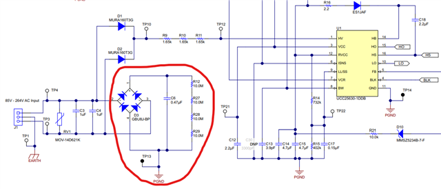
I'm having some issues with this UCC256404 design:

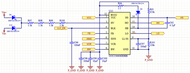
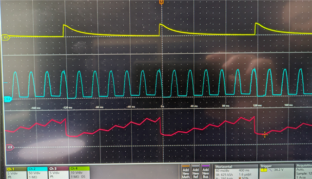
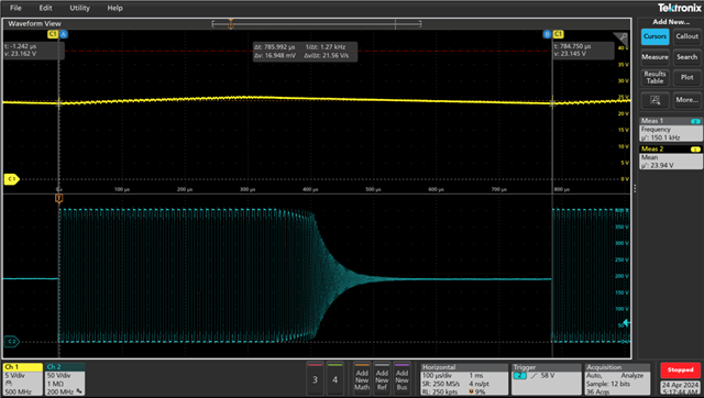
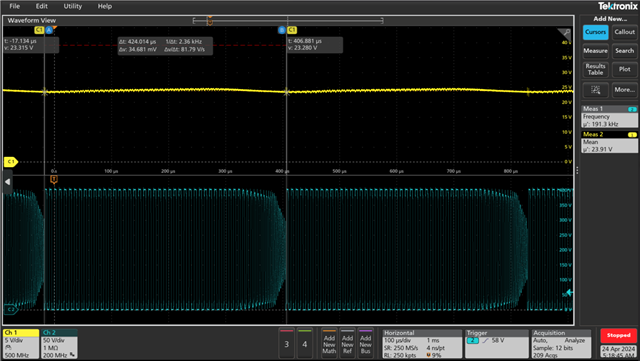
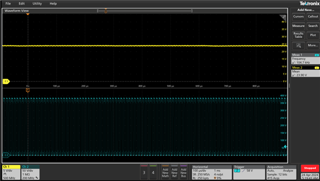
LLC_EN is set to 0 V so the switching is disabled. When the AC is connected (Vin+ and Vin-), these are the waveforms for the HV and RVCC pins:

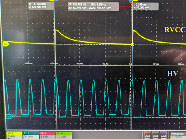
RVCC reaches around 12 V, but it restarts every 120 ms. And the voltage at the HV pin is a half-wave rectified sine wave.

The flat portion of the HV waveform just after RVCC starts is 0 V, but then it raises every cycle (10 V, 13 V, 16 V, 19 V and 21 V). The dataseet says the zero crossing is detected around 9 V, so that may explain why RVCC resets continuously. However, shouldn't HV be a full-wave recitified sine wave? And why is it not reaching 0 V all the time? Thanks in advance for your help!

  • Hi Marcos,

    Before I answer your question, could you please share the schematic around VCC pin. I would like to see the cap values and the components its connected to? Also, Could you show the VCC waveform too along with above waveforms.

    Regards

    Manikanta P

  • Hi Manikanta,

    Sure, this is what is connected to the VCC pin:

    And this is what the VCC voltage does (red curve):

    It reaches around 25 V and then it resets. I'm forcing BLK to 0 V (I would like to use this pin as an enable signal), but even if I put 3 V on this pin, the converter doesn't start switching. 

  • Hi Marcos,

    Could you share the whole schematic? the rectified voltage should be fully rectified voltage.

    Regards

    Manikanta P

  • Hi Manikanta,

    Thank you for your message. I think I found the issue. I don't have this section (marked in red) in my design:

    I did some simulations and without these components, the voltage at the HV pin is a half-rectified sine wave, but with these components it becomes a full-rectified voltage.

    I'll be able to add these components tomorrow. I'll post the new waveforms as soon as get some results.

  • Hello! I added a full bridge rectifier like in the schematic shown in my previous post and now I get a full rectified waveform for the HV pin voltage, but just for a few cycles:

    After the initial cycles, the waveform gets distorted with an offset, so I don't think the IC is detecting the zero crossing. This is caused by the controller IC (I removed it and there is not distortion). I tried a second board and I get the same result. I'm still keeping BLK at 0 V, but setting BLK = 2 V doesn't make any difference and the LLC converter doesn't start switching. RVCC and VCC keep resetting way faster than 1 second, so I don't think the IC is detecting a fault. It may not be detecting the mains and forcing the X-capacitors discharge. Any idea what may be causing this? Thank you!

  • Hello,

    Your inquiry has been received and is under review.

    Regards,

  • Hello,

    Your waveform looks like you have some filtering on the HV pin.  When the HV pin stars drawing current it attenuates the sing wave.

    Could you please share the schematic for review?

    Regards,

  • Hi Mike,

    Thank you for your message. I had the same thought, but the HV pin doesn't have any filtering elements attached to it. You can see the schematic on my first post.

    However, I managed to get the LLC started! And when it starts switching, the HV voltage transforms to the nice full-wave rectified sine wave.

    I'm on holidays next week, but I'll post more information and the HV waveform when I'm back. Thanks a lot for your help with this issue!

  • Hello,

    Thanks for letting me know and have an nice Holiday.

    Regards,

  • Hi Mike,

    I'm back from holidays, thank you for your patience. As I said on my last post, the HV pin voltage looks good when the IC starts switching. I've been testing the LLC converter and I'm able to take all the power from it, which is really good. And the thermals look okay too!

    The only small issue that I'm having now is that it enters burst mode all the time, even when I'm taking the full load from it. I'm not really sure why this happens. I attached the Excel file with the calculations. If you think it's better to create a new thread, just let me know. Thanks a lot!  1440.UCC25640x Design Calculator Rev4.0.xlsx

  • Hello,

    If you are at full load and the converter is bursting.  More than likely you are hitting an over current protection mode fault reset.

    I would check your ISNS divider to make sure it is setup correctly.  The ISNS resistor might be too large for your design.

    Regards,

  • Hi Mike,

    Thank you for your message. I reviewed the design following the "1440.UCC25640x Design Calculator Rev4.0.xlsx" Excel document, but I still can't figure out why the converter stops switching periodically. These are 2 waveforms that I took this morning. The first one is at 50% load (5.5 A), and the second one is at full load (11 A). The yellow signal is the output voltage (24 V), and the blue one is the drain-source voltage across the bottom MOSFET on the primary side:

    However, I can make it switch continuously if I reduce the input voltage. For example, this is at full load at 375 V input voltage instead of 400 V:

    I'm not sure it's an over current protection, since it happens for small loads too. But I'm not sure if it could be a burst mode issue either.

    Any help is much appreciated!

  • Hi Marcos,

    Looks like the controller is operating in burst mode. You can adjust the VCR caps and/or Burst mode settings to avoid this situation.

    Regards

    Manikanta P

  • Hi Manikanta,

    You were right, I adjusted the VCR caps and it's working perfectly now. I really appreciate you and Mike's patience. Thanks again for your help!

    Marcos.