This thread has been locked.

If you have a related question, please click the "Ask a related question" button in the top right corner. The newly created question will be automatically linked to this question.

TPS274C65CP: Current limit resistors and protection questions

Part Number: TPS274C65CP

The two available versions only differ in current-limit setting ranges, where only the H-version can support true 2A-operatiion by setting the respective current-limit range with 110kOhm 1% resistor.

What happens when:

1. other values than the recommended ones or values with greater tolerances are being used?

2. no resistor at all is being connected to pin 30? 

3. pin 30 is shorted to GND?

4. How much energy does the TPS274C65CP internal clamp on the output pin dissipate max? (Would it allow to eliminate the usually used 600W TVS that needs to be present in older BTS5210 designs?)

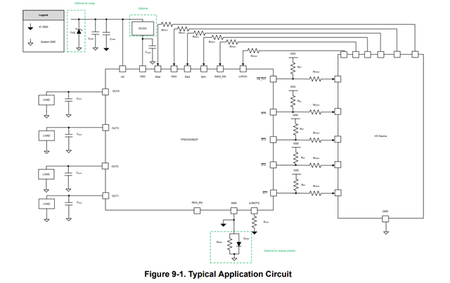
5. When implementing the reverse protection ground, do any pin-to-ground connections attach to the pin 21 chip GND signal or the V- power supply signal?  The TPS274C65CPEVM schematic shows pin pull down resistors connecting to V- and only the PowerPad is connected to pin 21.

BR, Walter

  • Walter,

    Find the answer to the questions below:

    1. The device is not guaranteed to limit at the specified current limit. Chances are that it will limit at the specified current limit, however given the design margins there could be a case where the worst case scenario occurs as far as tolerances and the "neighboring" current limit is used.
    2. The highest current limit threshold (110kOhm) is used
    3. The lowest current limit threshold (13.3kOhm) is used
    4. While we do some system level tests for validation at 100mH, the actual capability of the internal VDS clamp is going to be a product of the load current and inductance on the output. It could potentially replace the TVS diode, however it depends on the energy that is begin dissipated. Do you have a load profile for reference?
    5. The EVM has a lot going on in order to provide functionality and an easy user experience, however from a conceptual point of view I would use the reference schematic in the datasheet:

    Maybe I am missing the question- however are you asking for unused pins (for example if you are not using DIAG_EN), can you tie these directly to ground? The recommendation is to either float the pins (the digital pins have internal pull-downs) or to explicitly pull them down with RPROT. There are ESD cells on the digital pins so any voltage above the recommended/abs max conditions in the datasheet (which would occur in reverse polarity) would potentially bias the ESD cells and cause damage. 

    Best Regards,
    Tim