


We're using the above design in our design. During load testing I discovered that the battery wasnt actually charging.
Stat1/2 PG is read by a micro controller and some GPIO based LEDs are currently relaying the status during testing.
Firstly datasheet isnt entirely clear. PG is named as Active low, but Stat 1/2 are not. But reading in the datasheet, it appears open drain is active when the status is marked as ON. So in my code interoperating the status, I'm reading as Active low.
Im running the 12V source from a bench power supply, and using a DMM for finer current reading.
When I turn the project on, I get around 10mA draw from the 12V supply. roughly 3-5mA of this is going to the indicator leds.
When theres no battery connected. the STAT 1 and 2 are both lit, indicating the open drain is active.
When a battery in connected STAT 1 is still lit, STAT2 is off. Indicating 1's open drain is active, 2 is off.
More importantly. Apart from a 1 or 2mA difference accounting for the led change. There is no significant increase in power draw to show the battery is charging.
I have tested this on batteries with middling charges of 3.5V.
If this was in the faster charging mode as indicated, the power draw will be around 100mA from the PSU. not 10mA
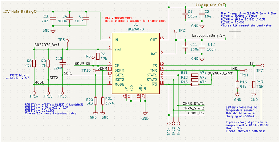
ISET1 is set for 300mA charge current.
Ive been scratching my head on this one for a while, and ran out of ideas.
I have tried increasing the charge current to 1A by swapping the ISET to a 1K resistor, that made no difference. I even removed and completely bypassed some battery protection circuitry we had (not shown here) in case that was doing it... I have checked soldering from the Fab house. All appears as it should.
Can anyone see the problem in this circuit design?
PS there is a 33uF cap closer to the battery not shown in this screen grab.
Thank you in advance.
*ADDED INFO*
2 more additional steps have been tried. Another of our engineers discovered 2 possible causes based from notes in the datasheet.
- ISET1 220nF capacitor should pull-up to BAT not VREF "A 0.22-μF capacitor connected between BAT and ISET1
is recommended to improve operation at low charge currents." - recommended 10nF capacitor missing from DDPM to GND "CDPPM of 10 nF was added to prevent the IC from falsely entering short circuit protection at start-up.
However after hot wiring these fixes to our prototype, nothing has changed. Batteries still not charging.
