Hi Team,
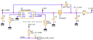
customer is observing a Pre-charge to fast-charge transition threshold of 1.54V instead of the 2.5V claimed in the DS.
The battery was simulated by a H-bridge power supply.
Would you know what could cause this deviation?
BR,
Stefan
Hi Team,
customer is observing a Pre-charge to fast-charge transition threshold of 1.54V instead of the 2.5V claimed in the DS.
The battery was simulated by a H-bridge power supply.
Would you know what could cause this deviation?
BR,
Stefan