This thread has been locked.

If you have a related question, please click the "Ask a related question" button in the top right corner. The newly created question will be automatically linked to this question.

TPS23754: Using Coilcraft POE40Q-24ED with TPS23754-substitute for Coilcraft POE300F-24L

Part Number: TPS23754

HI All,

We've got a current design using the TPS27354 (250kHz) and the Coilcraft POE300F-24L and it is working well in mass production.

However we have a smaller board to use the TPS23754 on, and the POE300F-24L transformer is much too large.

The substitute we wish to use is POE40Q-24ED (48V @ 1.5A). The  POE40Q-24ED is much smaller, and is designed by Coilcraft for POE Flyback.

We've substituted the POE40Q-24ED transformer correctly in the footprint of the POE300F-24L and are experiencing difficulty, i.e., the 23754 does not like the  POE40Q-24ED transformer.

We realize the DCR max values are not matching perfectly, but being these transformers were designed to work with this type circuit (250kHz), we're wondering if anyone else has experience with substituting the  POE40Q-24ED transformer in an existing  TPS23754 based design?

We believe the original design by another engineer using the POE300F-24L xfmr was a reference design?

We haven't begun to troubleshoot yet but the TPS23754 we believe is damaged.

Any help is appreciated.

  • Hi Ray,

    Thanks for reaching out.

    We will check your questions and get back to you by the end of this week.

    Best regards,

    Diang

  • Thank you Diang,

     The POE51Q-24ED transformer is now operating in the prior design with same results same waveform on primary as the original transformer, compared side by side with no component changes to prior design values.

    What I'd like to know now is how to "fine tune" the design. It's running now and providing the 24VDC at the VA I require.

    I started out with the POE51Q-24ED as that's a higher VA and I deem it to be more reliable at the lower VA I will be running it at. 

    My goal is to have a POE supply that will run at the maximum POE+ power levels without reliability issues. 

    Our design is for audio amplification so the duty cycle will definitely be low, as music is high crest factor.

    There will be no "ORING" of the supply with outside DC.

    I would have like to attach better images of the primary waveforms but our security will not allow me to link a file on our network with outside.

    So, a cut and paste is the best I can do.

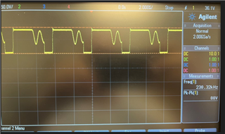
    This 1st  image is of the new POE51Q-24ED primary waveform at the FET driving the primary of the xfmr.

    Seems there is a little "hang/glitch" after the small sinusoidal waveform before the waveform goes to 0.

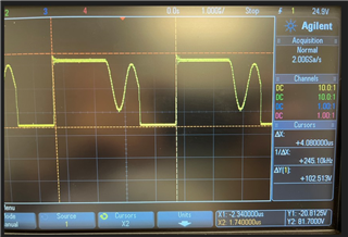
    This 2nd image is of the original POE300F-24L_ primary waveform at the FET driving the primary of the xfmr.

    Ignore the scale, my tech didn't get that adjusted, but you can see the similarity.

    Thanks!

  • Hi Diang,

    I have found SLVA305 and it is a great help, however, I still need an analysis of my switching waveform, as it tells the entire tale...

  • Hi Ray,

    Thanks for your update. 

    Looks like you need a 24-V Class-4 power transformer.

    POE40Q-24ED is supposed to be more suitable compared to POE51Q-24ED for your cases considering the inductance of POE40Q-24ED is higher. The flyback converter goes into discontinuous mode when the current drops to 0 A on the secondary rectification. The larger inductance will offer shorter discontinuous mode time and potentially lower RMS current for better efficiency. 

    POE300F-24L_: 42 uH

    POE40Q-24ED: 27.8 uH

    POE51Q-24ED: 22.2 uH

    When it goes into oscillation, the leakage inductance of these transformers will take effect.  

    Best regards,

    Diang

  • Thanks Diang,

    Our 24V is SMPS to 5V for a processor PMIC, and also to a separate 3.3V for DSP and various other devices, so secondary current will never go to 0 A. (if that's what you're talking about) vs. "0" on the secondary rectifier switching waveform?

    We actually do not need the higher current of the 51Q transformer anyway.

  • Hi Ray

    Thanks for your reply.

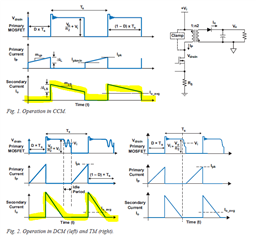
    Sorry for the confusion. I mean the 0-A is when the "secondary current" goes zero as shown in the attached picture, and the flyback converter will go into DCM. Then there will be oscillation on the Vds. The oscillation in DCM normally won't cause issue for the converter. Theoretically POE40Q-24ED could be better than POE51Q-24ED for your power rating for the larger inductance. 

    Best regards,

    Diang

  • Hi Ray,

    Since we did not get back from you for a long time. I will close this thread for now. Please reply or open a new thread if you have further questions.

    Best regards,

    Diang