This thread has been locked.

If you have a related question, please click the "Ask a related question" button in the top right corner. The newly created question will be automatically linked to this question.

TPS548D22: about RCSP_FSEL

Part Number: TPS548D22

Hi
Dear All

Now, I'm designing circuit use TPS548D22.

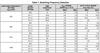
TPS548D22 is setting output voltage=0.71V, f=650kHz, input voltage=12V.
I am looking for better transient response.

From the measurement results, RCSP_FSEL[1:0]=01(Rx1) was better than 00(R/2).
However, 0.71V seems to be the correct setting for R/2 from Table 7 Switching Frequency Selection in the datasheet.

Is there any problem using RCSP_FSEL[1:0]=01?
Also, please let me know what is affected.

Best Regards

Kentaro Iba

  •  

    The output voltage transient response of the TPS548D22 depends on the internal ramp selecting, inductor value, feedback divider attenuation and the output capacitance.

    For low voltages, the overshoot is generally limited by the large-signal response limitation of 0% duty cycle, since the converter can't generate a negative duty cycle.

    This is 1/2 x ΔIout^2 x L / (Vout x Cout)

    So, if you are looking to improve the overshoot response to a drop in load, you may have to look into increasing Cout.

    The undershoot in response to a load step (increase) is driven by:

    ΔIout x Vout/Vrsp x L /(8 x tau)

    where Vrsp is the regulation voltage at the RSP pin and tau is the ramp time constant for the ramp and switching frequency options, which can be found in table 7 of the datasheet (https://www.ti.com/lit/ds/symlink/tps548d22.pdf#page=25

    For 650kHz the time constants are 7μs, 13.5μs, 25.9μs, 44.5μs

    Each increase in the ramp time-constant reduces the injected ramp amplitude, which improves the transient response, increased the minimum output capacitance required for stability, but also increases the pulse frequency jitter.  If you have sufficient output capacitance to keep the output impedance (Zout) of the capacitors below Vout/Vrsp x L /(8 x tau) by 1/4 of the switching frequency and above, the loop should be stable and ramp selection would be a matter of switching frequency jitter tolerance.

    In addition to ramp selection, you can also look at the VSEL option you've used.  For a 0.71V output, selecting the 0.6992V reference so that Vout/Vrsp is as close to 1 as possible will also improve transient performance.

    Alternately, selecting a smaller inductor value which allows more ripple and faster slewing of the inductor current would also improve transient performance without the increased jitter resulting from the higher ramp time-constant.

  • Dear Peter
    Thank you for your response.
    I'm very grad.

    My problem is undershoot in response.

    I want to use ramp select is 13.5μs(RCSP_FSEL[1:0]=01) on my design PCB.

    > If you have sufficient output capacitance to keep the output impedance (Zout) of the capacitors
    > below Vout/Vrsp x L /(8 x tau) by 1/4 of the switching frequency and above, the loop should be stable and ramp selection
    > would be a matter of switching frequency jitter tolerance.

    Please teach me about:
    Now, 470uF x2(SP-CAP capacitor), 100uFx2(Ceramic capacitor)on my design.
    [If you have sufficient output capacitance ] -> I have sufficient output capacitance.

    Q1. [the output impedance (Zout) of the capacitors] is capcitor ESR?

    Q2. What does [Vout/Vrsp x L /(8 x tau) ]  caluculate?
    Q3. 1/4 of the switching frequency is 162.5kHz?(from 650KHz/4)

    Best Regards,
    Ketaro Iba

  • Q1. [the output impedance (Zout) of the capacitors] is capcitor ESR?

    Zout is more than the ESR of the output capacitance, it's the absolute value of the complex impedance of the capacitor.

    Sqrt ( (1 / (2 x pi x Cout x F) ^ 2 + ESR ^ 2)   Where F is the frequency the impedance is being evaluated at.

    Multiple capacitors in parallel will have their impedances add like parallel resistors.  Zout(total) = 1 / (1/Zout1 + 1/Zout2 + 1/Zout3...)

    Q2. What does [Vout/Vrsp x L /(8 x tau) ]  caluculate?

    That calculates the peak dynamic output impedance, which is also the output impedance at Unity-Gain cross-over.

    Q3. 1/4 of the switching frequency is 162.5kHz?(from 650KHz/4)

    Yes.

  • Dear Peter
    Thank you for your advice.

    I caluculate Zout and decide RCSP_FSEL[1:0]=01 or 00.

    Best Regards,

    Kentaro Iba

  • Dear Peter
    Thank you for your advice.

    I caluculate Zout and decide RCSP_FSEL[1:0]=01 or 00.

    Best Regards,

    Kentaro Iba