Because of the holidays, TI E2E™ design support forum responses will be delayed from Dec. 25 through Jan. 2. Thank you for your patience.

This thread has been locked.

If you have a related question, please click the "Ask a related question" button in the top right corner. The newly created question will be automatically linked to this question.

BQ25306: or BQ24171 or bq24640: Lithium-Ion Capacitor chargers ? Which protection circuits ?

Part Number: BQ25306
Other Parts Discussed in Thread: BQ24171, , BQ24640, TPS3840, BQ25173

Hello to all the TI support team, and thanks for your help! Sorry in advance if my question has already been asked elsewhere, but I couldn't find answers to my questions. I'm also a bit new to the PMIC charger world!

I'm currently trying to design a single Lithium-Ion Capacitor (LIC) charger circuit. I plan to use this capacitor as my main power source on a standalone circuit

Datasheet of the LIC: datasheet.lcsc.com/.../2109031130_CDA-LIB1840Q4R0118_C2891403.pdf

Characteristics:

  • 2,5V < Vcap < 4V
  • 6A rated current, 40A max
  • 1100F ~ 450mAh (4V to 2.5V discharge)
  • As for Li-ion batteries, no discharge below low voltage limit allowed (2.5V)
  • Lower self discharge than conventional EDLCs

Circuit characteristics:

  • Completely standalone : no I2C, no USB, no hand or user access on the circuit
  • RC settable charging voltage (4V here, but I'd like to be able to change that if I use another capacitor in the future). Same for current
  • Main circuit can be operating or shut-down during charging, no preference
  • Main voltage = 9V (Low Iq boost converter will be added on the circuit)
  • Capacitor disconnect & low current draw (~1µA if possible) when it reaches the low voltage limit

I've had a hard time finding a charging circuit fitting the voltage & current requirements for this kind of application! So far, I've seen that the BQ25306 charger might fit some of my needs, having a RC settable charging voltage. BQ24171 also seems like an option, perhaps a bit more complicated. Both also have limited charging current (3A to 4A max). I've also found the Supercap charger bq24640, but the "sleep" current seems a bit too high (25µA, which is low regarding EDLCs capacitors, but a bit more problematic for LICs)

With all that in mind, I still have some questions:

  • Will those circuits work as LIC charger circuits?
  • If i use the bq24640, can I put a high power low reverse current diode in series with the charging path (taking into account the voltage drop) to reduce return current in the charging circuit when it enters sleep mode?
  • Which protection circuit can I add to ensure custom at least OVP (4V), UVP (2.5 - 2.7V) and undervoltage charging prevention on the capacitor? overcurrent charge & discharge are optional, but appreciated (same requirements, RC settable if possible).

Thanks again!

Germain

  • Hi Germain,

    I recommend BQ24640 with the reverse blocking diode to reduce leakage.  See app note that addresses leakage current of this charger family at https://www.ti.com/lit/pdf/slva829.

    I am not aware of any protection ICs that are standalone/RC settable.  So you will have to design your own with series PMOS FETs controlled by SVS circuits here:: https://www.ti.com/power-management/supervisor-reset-ic/overview.html.

    Regards,

    Jeff

  • Hello Jeff,

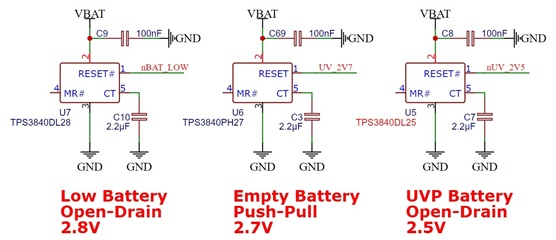
    Thank you for your answer, and sorry for the late reply! I eventually realized that I will have current limitation on the input of my charger IC anyway (the connector I have to use won't handle more than 2 to 3 Amps). To reduce BOM cost & schematic complexity, I'd rather use the BQ25306, if possible. I've added some supervision circuits as you suggested, based on different versions of the TPS3840: 

    nBAT_LOW will drive a LED connected to the boost output, UV_2V7 will drive the gate of a PMOS in serie between by battery & boost input, and nUV_2V5 will probably shunt ICHG to the ground to trigger a "FAULT" condition on the charger and prevent it from charging a completely depleted capacitor.

    First question : will this kind of solution work? I'm foreseeing two problems with it, though:

    • I would prefer an "empty battery" flag at 2.8V (and "Low battery" flag at 2.9V), as it will give the user more time to re-charge the capacitor before its self discharge drives it below 2.5V. I also would prefer a push-pull "active high" circuit to drive the PMOS, as it will limit the current draw when the UV condition is triggered. The correct reference from the DS would be TPS3840PH28, but it doesn't seem to be available. Do you know why?
    • If I set the max capacitor (~battery) voltage to 3.9V, and I try to charge a fully depleted capacitor (2.5V), I'll be below the 0.7*3.9 = 2.73V threshold below which the charge current will be only 10% of the max allowed charging current. Can I set one of my UV flags (say, nBAT_LOW) to trigger a PMOS, modifying the equivalent resistor of my Bat voltage resistor divider measurement circuit, in order to lower V_BAT_LOW below 2.5V and start charging with maximum current ? Does the BQ25306 support "on the go" Bat Voltage FB modification?

    Here is my proposed charger circuit, with my suggestions. Could you please tell me if you think this might work?

    Thanks !

    Germain

  • Hi Germain, 

    Firstly, for your reference here is an application note we have regarding charging supercapacitors  https://www.ti.com/lit/pdf/sluaao7 .

    I also want to point out another possible option. BQ25173 is another charger specifically designed for supercapacitor charging, but its max charge current of 800mA may be lower than your design requires. Our chargers designed for supercapacitors do not have the issue you brought up regarding reduced charge current at low "battery" voltage.

    In terms of your proposed BQ25306 design "on the go" modification of FB is supported. I recommend you test its implementation on your unique PCB, but in theory your proposed method should work to begin charge with maximum current. 

    For questions relating to the TPS3840 and related circuit I recommend creating a new thread. It will allow the appropriate expert for that specific device to best support. This thread can continue to be used for questions regarding the charger IC. 

    Best Regards,

    Garrett 

  • Thanks Garrett! I had already seen the application note you provided, it has a lot of very useful information, but it still has some limitation regarding the application I'm working on:

    - Linear charger BQ25173 seems great on a lot of points (including the possibility to disable the resistor divider wit PG\ to prevent leakage when the charger is disconnected), but the 800mA limit is a bit low for me... the same IC with internal FETs / buck topology allowing 3-4A charging would be a game changer! (even more with an integrated disable function for the FB resistor network, same as on the BQ25306).
    - the BQ24640 seems super versatile, but a bit overkill for my application (and needs the reverse diode to block leakage current from capacitor). I might use it in the end, if that doesn't increase BOM cost & board occupancy too much
    - The other Li-ion chargers suggested need a host I2C connection to be used to their full potential (including the trickle & pre-charge bypass)

    Thank you for your review on my schematic, I'll try to implement that! No problem for leaving the supervisors circuits questions out of this thread!

    Best regards,

    Germain

  • Hi Germain, 

    Thank you for the feedback regarding the different charger ICs proposed.

    Please let us know if you have any additional questions. 

    Best Regards,

    Garrett