This thread has been locked.

If you have a related question, please click the "Ask a related question" button in the top right corner. The newly created question will be automatically linked to this question.

BQ25896: Charging current is too small

Part Number: BQ25896

Hello

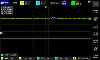
I'm using bq25896 in a device I'm developing, and I have trouble figuring out why I get too little charging current. ICHG register reports 450mA when the battery is almost empty, then it gradually goes down to 100mA when VBAT is 4.1V, and by that point charging stops. I am positive that the power supply is not overloaded, USB tester shows that it happily provides over 1.5A when I connect my phone to it using the same cable.

https://e2e.ti.com/support/power-management-group/power-management/f/power-management-forum/938817/bq25895-small-charging-current-of-bq25895 seems to be a similar issue, but it was never followed up.

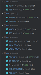
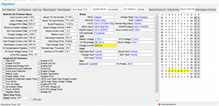
During the device initialization I reset the charger (REG_RST = 1), disable watchdog (WATCHDOG = 0), enable periodic ADC conversion (CONV_START = 1, CONV_RATE = 1), set charge current limit to roughly 1A (ICHG = 1000 >> 6 = 15, results in 960mA) and enable charging (CHG_CONFIG = 1)

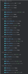
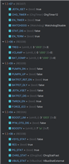
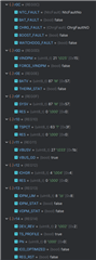
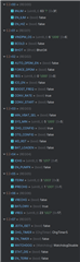
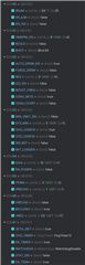
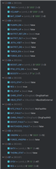
Register dump after about a minute of charging:

  • Hi Pavel, 

    Thank you for reaching out via E2E. Please see my comments below. 

    Upon review of your register dump I see the input current limit reported in REG13 = 500mA. A 500mA current limit would explain why you only see at most 450mA charging. The log also shows REG00 sets input current limit to 3.25A. 

    For debug purposes I recommend disabling the ICO feature (REG02 bit 4 = 0) then verify if input current limit reported in REG13 matches the input current limit set in REG00. With this higher current limit you should be able to observe charge current = 960mA as you have set. 

    Best Regards,

    Garrett 

  • Disabling ICO_EN didn't do anything.

    Right now I observe IDPM_LIM = IINLIM = 3250mA, but ICHGR is 0

  • Possibly it was because of low charge level, now both IDPM_LIM and IINLIM still report 3250mA, but ICHGR is at 250mA anyway

  • Hi Pavel, 

    For the most recent register dump the registers after REG0F are not included. Can you please help to add? Additionally if possible for any future register dumps can you please just provide the raw hex value for each register rather than break it apart into each individual bit settings. 

    What value resistor do you have connected to ILIM in your design? I am wondering if that may be limiting the available current. 

    Can you also provide a waveform showing VBUS and VBAT at the time when you are only charging at 250mA? 

    Best Regards,

    Garrett

  • Sorry, here's a new full register dump:

    r00  r01  r02  r03  r04  r05  r06  r07  r08  r09  r0A  r0B  r0C  r0D  r0E  r0F  r10  r11  r12  r13  r14
    0x3F 0x06 0x41 0x1A 0x0F 0x13 0x5E 0x8D 0x03 0x44 0x73 0x56 0x00 0x12 0x51 0x52 0x3F 0x98 0x05 0x3F 0x06

    I have suspected the ILIM resistor already and even replaced it with one of smaller value that it was originally, to 220 Ohm, which should result in setting of 390/220 = 1.77A. Writing 0 to EN_ILIM register does nothing as well.

    I will be able to look at waveforms a bit later.

  • Hi Pavel, 

    Thank you for sharing. I can confirm based on the newest register dump I see no clear reason for charge current limitation based on register settings and status indicators. 

    I have a couple additional requests beyond VBUS and VBAT waveform. 

    -Can you please share your schematic for me to review. 

    -You originally said you can observe 450mA, now you observe 250mA (according to the ADC). Do you every observe higher charge current? If you change the ICHG setting to say 192mA setting (REG04 = 0x03) does actually charge current match ICHG setting? 

    Best Regards,

    Garrett 

  • I said that I observe 450mA at max, when the battery is almost discharged, which gradually drops down during the charging process.

    When I set ICHG to 192mA, reported charge current drops down to 150mA from 350mA right before.

    Here's the charging circuit:

    I also have a suspicion that integrated battery protection IC may limit charge current, will try removing it out of equation

  • No change with a battery without a protection PCB

    Are there guides on how to measure waveforms?

  • Hi Pavel, 

    Thank you for providing the schematic and running the test with protection PCB removed. 

    I have reviewed the schematic and see no clear issue. I have a couple additional questions. 

    -Do you only have 1 prototype board or multiple? If you have multiple is the low charge current behavior consistent? 

    -Do you happen to have an alternate battery you can test with to verify the behavior is consistent with a different battery? 

    I said that I observe 450mA at max, when the battery is almost discharged, which gradually drops down during the charging process.

    This is not expected unless the device is being thermally limited or current limited, but register status does not indicate either. When battery voltage is between 3V and 4.2V device is in fast charge stage and charge current should remain relatively constant, as shown in figure 12 in the datasheet. 

    Are there guides on how to measure waveforms?

    Typically customer has freedom to use tools available to them. Whether that be an oscilloscope or some other tool for measuring and plotting voltage. 

    Regards,
    Garrett 

  • Do you only have 1 prototype board or multiple

    I have just one assembled board

    Do you happen to have an alternate battery you can test with to verify the behavior is consistent with a different battery? 

    I have already checked different batteries, of different capacities, with and without integrated protection ICs: results are the same.

  • Here's what I managed to measure, but I'm not sure what I am looking for, and even whether my oscilloscope is enough for the task.

    CH1 is VBAT, CH2 is VBUS. When I disconnect VBUS, the ripples on VBAT disappear.

  • Hi Pavel, 

    I have just one assembled board

    Apologies I should have asked my original question a different way. Even though you only have 1 assembled board do you have the ability to test with other BQ25896 ICs? It will be helpful to know if this behavior is consistent across multiple parts or only on the one IC. 

    Best Regards,

    Garrett 

  • do you have the ability to test with other BQ25896 ICs

    I already have replaced a couple thinking maybe specific chips were faulty, no luck

  • Hello Pavel,

    Can you share your layout files as well so we can review? And pictures of your bench setup if possible.

    Our suspicion is that the BAT pin voltage on the charger may be too high and the charger is actually going into CV too early. This would explain the behavior of the charge current being highest at low battery voltage and slowly tapering. If the battery power path has high impedance to the cell terminals it can lead to this type of behavior. Traces and wires connecting from the battery to the charger should be as short as possible and thick as possible for minimum IR losses from the battery to the charger.

    Sincerely,

    Wyatt Keller

  • Here's the layout (BATT+ trace length is about 7mm), the battery is then currently connected through an XH2.5 connector with ~6cm of 20AWG wires. I'll try to shorten them and solder them closer to see if anything changes.

  • Hello Pavel,

    Thanks for sharing your layout, please confirm the voltage as close to the charger IC as possible to verify the charger is in voltage regulation.

    Sincerely,

    Wyatt Keller

  • VBAT reported over I2C during charging matches what I measure with my multimeter within .02V, I'm putting probes directly at solder blobs of the IC

  • Hello Pavel,

    Please define the test conditions when you made the VBAT measurement, is this during the 400mA charge? What were the other voltages of the system? (VSYS, VBUS, current if possible)

    Sincerely,

    Wyatt Keller

  • Right now:

    Reported charging current: 300mA

    Reported/measured VBAT: 3.684V / 3.696V

    Reported/measured VBUS: 5.0V / 4.985V

    Reported/measured VSYS: 3.724V / 3.719V

    Registers (values are a bit different here, a few minutes have passed):

    r00  r01  r02  r03  r04  r05  r06  r07  r08  r09  r0A  r0B  r0C  r0D  r0E  r0F  r10  r11  r12  r13  r14
    0x7F 0x06 0x41 0x1A 0x0F 0x13 0x5E 0x8D 0x03 0x44 0x73 0x56 0x00 0x13 0x46 0x47 0x3F 0x98 0x06 0x3F 0x06

  • Hello Pavel,

    I will take a look at your data and respond by the end of today.

    Sincerely,

    Wyatt Keller

  • Hi Pavel, 

    Below image is a screen grab of the TI GUI showing all current register statues. I have tested with your exact register settings, as well as, closely replicated your input voltage and battery voltage. The BQ25896 charges at 0.96A as expected and will also charge at 2A default with all settings unchanged besides ICHG. 

    Unfortunately at this stage of debug our best conclusion is the low charge current is somehow related to your board design. The BQ25896 has been released to market for close to 10 years and does not have a know issue involving charge current regulation. 

    Have you checked if you can pull a more current from the converter by either increasing SYS load or slowly increasing ICHG setting (assuming that is safe to do with your battery)?

    Best Regards,

    Garrett