This thread has been locked.

If you have a related question, please click the "Ask a related question" button in the top right corner. The newly created question will be automatically linked to this question.

WEBENCH-POWER-DESIGNER: Flyback transformer turns calculation seems not to match datasheet formulas.

Part Number: WEBENCH-POWER-DESIGNER
Other Parts Discussed in Thread: UCC28C54

Hi

I have a WeBench related question regarding a design that WeBench made and how WeBench performs the calculation of turns ratio for a flyback transformer.

It concerns a design for the UCC28C54.

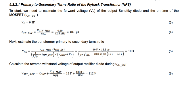
According to the data sheet, the primary to secondary turns ratio is calculated as

NPS = VIN_MIN × tON_EST / ( (1/fSW − tON_EST) × (VOUT + VF) )

Where tON_EST is given by 

tON_EST = DVIN_MIN / fSW

Now, the WeBench design gives the following data 

DVIN_MIN = 37,291

fSW = 41.951 kHz

VIN_MIN = 311.124 V

VOUT = 12 V

VF = 1,05 V

Calculating for Nps with the data given from the WeBench design using the formulas in the datasheet, gives Nps = 14,2

BUT, thee WeBench design states Primary winding 119 turns and secondary winding 12 turns, which gives Nps = 9,9

Can you please explain this big difference? 

I have attached the concerned WeBench design for reference.

Thanks, Thomas Nilsson

0825.WBDesign5.pdf

  • Hi,

    Can you show each equation in your message the equation # in the datasheet, and page #, if you made additional development also show how your additional development is?

    I am not able to relate your equations to the datasheet equations although you said they were from the datasheet. After you relate your equations to the datasheet equations so I can know the one is from which one in the datasheet, I may provide my comment. Now I am not able to understand where your questions are from the datasheet. 

    For example, the datasheet shows Nps as below

    But your message shows

    I cannot find this equation, also cannot find tON_EST, where did you get these? 

  • Hi,

    The input voltage range and the output voltage are different, also the secondary voltage VF assumed different. Can you show your calculation in detail to help understand where possibly the difference comes from?

  • The values I have listed are the same as in the webench design. Using these values to calculate turn ratio using the datasheet formula does not give the same turn ratio as specified in the webench design. 

    Why is there such a big difference?

  • Hi,

    With the below and Vin = 220V, then Nps = 9.9 from both datasheet and the webench. It looks you are using Vin_min = 311V while the webench shows min 220. But you should use 220V if that is your Vin_min. It looks to me webench estimated Vbulk min = 220V while you estimated Vbulk = Vin_peak which is quite optimistic for design unless you use very large input bulk capacitance.

    But it looks the reason is Vin bulk value assumed to use in each calculation.

    DVIN_MIN = 37,291

    fSW = 41.951 kHz

    VIN_MIN = 311.124 V

    VOUT = 12 V

    VF = 1,05 V

  • 220 VAC min is the AC input = 311 VDC rectified, and the Webench schematic also shows the AC source which is named Vin.

    It is all in the webench design document that I attached in the first post!

    Also, if Vin_min is lowered, the turns ratio increases and the difference becomes even bigger!

  • Hi,

    When you have the load, the DC or bulk voltage is not the AC peak. But I think I have answered your question why Nps different. The webench assumed 220VDC and your assumed 311VDC. That is the reason. I think Nps = 9.9 should be used which with 220VDC may be a bit too conservative but better than your 311VDC which will not be achieved after the converter has load, and your design may result Vout out of regulation at full load and at 220VAC input. 

    Besides, 220VDC from 220VAC with practical bulk capacitor value is reasonable, but 311VDC from 220VAC would need unreasonable big bulk capacitor value, it may be too big to be practical particularly at full load when 220VAC.

  • Can YOU please show me your detailed calculation then, based on the formulas from the datasheet and the values you claim are the correct ones, that yields this result?
    Because I cannot get the numbers to add up and when I use your suggested values, on the contrary it gets even worse.
    Please also explain how I am supposed to get 220VDC from 220VAC!

    Not sure what you are on about regarding Cbulk, it is selected at 10uF, 400V and is well above the required input capacitance calculated, I haven't noticed anything unreasonable about that. 

  • Hi,

    The below is - the equations are based on the datasheet. You can check.

    If Cbulk = 10uF can work ok for you then no problem. But assuming Vin peak for Vbulk is not correct - the dc link voltage is not Vin peak but an averaged voltage - the webench assumes 220VDC by average is valid - yours 311V is not a practical assumption.

    But I have answered your question. How you pick up dc link voltage is at your option. I have pointed out why different Nps results from you. So this support is complete. If you have other support need, please start a new thread.

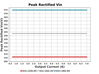
  • No, the question is not answered, because it is the DC voltage that is used in the Nps calculation, not the AC voltage. I have already listed, explained and showed that the VDCmin is 311 volt and why and that WeBench also lists this, and it is the same 311 V throughout the whole load-case from zero to full load, as you can see in the graph I already posted.

    If Vin is lowered to 220VDC this will affect the Duty-cycle and the sum of the lowered voltage and changed Duty cycle will result in a higher Nps. You can't just change one parameter and ignore all the rest. If you lower the Vin to 220VDC the Duty cycle will rise to impossible 56% and tON_EST will change to 13.4us, resulting in an increase in Nps. These parameters are all connected.

    311 volts is not an "assumption", it's a fact. Webench states this too.

    Like I said, the numbers don't add up in the Webench design using the datasheet formulas. So my question remains!

  • Hi,

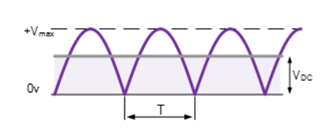
    The DC voltage is an AC voltage by average after rectification.  The voltage after rectifier is not a peak of ac but an average voltage and also depending on load and the rectifier output filter. The webench assumes 220VDC has no problem. 

    Please review the fundamental of ac-dc rectifier output voltage. It looks you mixed ac peak and average voltage of an ac-dc rectifier output with filter.

    You can get this below from many different literatures, the output voltage of a full bridge rectifier its DC is not its AC peak. I strongly suggest you review the fundamentals of ac-dc rectifier content.

  • You forget about Cbulk. And BTW, in your diagram above Vmin is 0V. The DC voltage indicated in the diagram is an average voltage, not a min voltage.

    Anyhow, like I already pointed out, if you lower Vin_min this will affect the duty cycle and tON_EST in such a way that the difference in Nsp will get even bigger. 

    Here


    Dvin = 1.847 * 1,55m*41951/220 = 0,546 --> 55% @ Vin = 220VDC

    tON_EST = 0,546/41951 = 13,1us

    NPS = VIN_MIN × tON_EST / ( (1/fSW − tON_EST) × (VOUT + VF) )

    NPS = 220 * 13,1u / ( ( 1/41951 - 13,3u)*(12+0,5) ) = 22,2 @ Vin = 220VDC


    In this case the dutycycle reaches 55%, which is not possible with the 28C54, 50% is max dutycycle.

    Webench lists dutycycle as 37.291%, unclear though at what condition, so I have to assume that it is at Vin_min as this yields the highest dutycycle.

    With Vin_min=311VDC the dutycycle calculates to approx 37%.


  • Hi,

    So it depends on how you choose bulk voltage and associated bulk capacitor. The Webench uses 220Vdc has no problem and you use 311Vdc is practically concerned. That is why you got different Nps - which was you wanted know why did not know - then I answered to you.

    I mentioned Cbulk several times. I showed the waveforms simply remind you your dc link voltage equals ac peak is not correct.

    Note Nps is to be calculated with all the assumptions used in the equation so affected when using a different Vdc. This is the reason and I answered to you. 

  • You forget about Cbulk. And BTW, in your diagram above Vmin is 0V, just like the peak is 311V. The DC voltage indicated in the diagram is an average voltage, not a min voltage.

    Anyhow, like I already pointed out, if you lower Vin_min this will affect the duty cycle and tON_EST in such a way that the difference in Nsp will get even bigger. 

    Here


    Dvin = 1.847 * 1,55m*41951/220 = 0,546 --> 55% @ Vin = 220VDC

    tON_EST = 0,546/41951 = 13,1us

    NPS = VIN_MIN × tON_EST / ( (1/fSW − tON_EST) × (VOUT + VF) )

    NPS = 220 * 13,1u / ( ( 1/41951 - 13,3u)*(12+0,5) ) = 22,2 @ Vin = 220VDC

    You can't just change the Vin value in one place and ignore the rest!


    In this case the dutycycle reaches 55%, which is not possible with the 28C54, 50% is max dutycycle.

    Webench lists dutycycle as 37.291%, unclear though at what condition, so I have to assume that it is at Vin_min as this yields the highest dutycycle.

    With Vin_min=311VDC the dutycycle calculates to approx 37%, with Vin_min=220VDC it calculates to impossible 55%.

  • Hi,

    The Webench still can use the same assumptions while also assuming 220Vdc as these assumptions are achievable and workable.

    Your original question is why Nps different between Webench and the datasheet - this question is answered.

    Vout + VF = D/(1-D) x (Vin/Nps) = (0.37/0.63) x (220 /9.9) = 13.05V = 12V + 1.05V so it is doable and match your specs - so no need to use your calculated 55%.

  • Why are you ignoring the fact that you are using different Vin values in the same calculation? This cannot be correct!

    It is not MY calculated 55%, it is according to your datasheet. Are you now saying the datasheet is wrong? Does the regulator not follow what is specified in the datasheet?

    The question is still not answered because the numbers do not add up with your explanation. Nps then becomes 22,2.

  • Hi,

    When using Duty = 0.37 and VDC = 220V (webench and datasheet equations), the Nps = 9.9. When using different VDC and duty = 0.37 then you get different Nps. 

    So that is why Nps difference comes from. 

    So 55% is ok to use and not need to use 55%. If you see 55% then you cannot use UCC28C54 as its max duty is up to 50%.

    So the webench has no problem, the datasheet has no problem. Both are correct and are matched each other. 

    Dvin depends on several parameters - which can be selected differently - then estimate to be at 37% is ok. 

    I am just to show you at 220VDC and 37% duty, both webench and datasheet can get the same Nps and the design ok to meet your specs 12V + 1.05V. A design does not have to pick up the same parameters as there are other possibilities can also meet the same specs.

  • Now you are saying that when calculating Duty cycle and tON_EST at Vin_min one should use 311VDC but when calculating Nps one should use 220VDC for Vin_min but at the same time use tON_EST and duty cycle calculated from 311VDC. It is contradictory and doesn't make sense. Vin_min is either 220VDC or 311VDC, it can't reasonably be both at the same time.

    Or, put in another way, why is Vin_min 311VDC when calculating tON_EST and Duty cycle and why is Vin_min 220VDC when calculating Nps and most importantly why are Nps calculated with Vin_min = 220VDC and at the same time using tON_EST and Duty cycle based on Vin_min=311VDC?

    Using two different values for the same variable in the same calculation just isn't right. How is one supposed to know what value to use where and when and what other variables in the design have several different values used in the same calculations?

  • Hi,

    A designer can do what they want as long as the design can work. I just show you how to get the same Nps which you did not know. So the same equations and the same pick up, then the same results. 

    Webench and the datasheet are on the same equations and the same results. Yours different is due to you picked up something different.

  • My question isn't about what a designer can do. My question is about the Webench values and how to make use of the information in the datasheet.

    If I can't understand how webench calculates or how to use the datasheet information then I can't calculate the design parameters for a design.

    You keep avoiding the obvious problem here - different values for the same variable are used in the same calculation. This seems totally wrong to me and I am still lacking an explanation on this. Vin_min simply cant be 220VDC and 311VDC at the same time. But apparently Webench has done it's calculation in this way. So either webench is wrong or the datasheet is wrong. I cannot see any other explanation and you still have not given an answer on this. Is the datasheet wrong and Vin_min should not be used when calculating tON_EST and Dvin_min? Because that seems to be what you are saying.

    In your table above you have specified tON_EST = 8.82 us both for Vin_min = 220VDC and for 311VDC, but tON_EST varies with Vin_min and cannot be the same for two different Vin_min values.

  • Hi,

    Already showed you how to get the same Nps based on the datasheet and match Webench, and meet your specs.

    There is no meaning to continue this thread. Your question is answered. I do not have other answers to you as the same equations and same values can give same Nps, and different values plug into equations different Nps can be resulted - that is the math there is no way to get other results. 

    Note this service is to help your design and as now how to get Nps based on the datasheet is provided to you - I do not understand your additional thoughts so I won’t be able to give other answers to you. In terms of this, I do not know what you want so not able to provide additional answer to this thread. Your other questions, if you still want to talk please create a new thread.

    Vout = 12V, VF = 1.05V, VDC = 220V, duty = 0.37, Nps = 9.9, VDC here is an average of Vin min peak = 311V with bulk capacitors. If any these changed a different Nps will be obtained.

  • What you showed uses two different values for the same variable in the same calculation. But no explanation on how that can be. Now you introduce a new term called "Vin min peak", but this term is not used in the datasheet nor in the webench design, are you suggesting that this value should be used instead of the Vin_min value in certain cases? Because that's what it seems like to me. In that case I guess it's the datasheet that is wrong.

  • Hi,

    Let's first clarify with the below:

    Vin is your input voltage, I will use the webench variables

    VinMin = 220V, AC, rms, and its peak VinMin_peak = 311V

    Vbulk is the voltage after the rectifier at VinMin, so its Vbulk_max = VinMin_peak = 311V

    Vbulk_average is with proper bulk capacitance at VinMin, assuming Vbulk_average = 220V, DC

    With the above,  it needs Nps = 9.9, Duty needs to be D= 0.37, based on this below equation to get VOUT = 12V and VF = 1.05V:

    VOUT + VF  = (D/(1-D) x (Vbulk_average/Nps) = (0.37/0.63) x (220/9.9) = 13.05V

    So Nps = 9.9 is ok to get exactly the required output voltage at assumed duty cycle 0.37. 

    So far the above is my understanding how Nps = 9.9 obtained by the wenbench.

    In the datasheet, if following the above, I would get the same result. That is why both the datasheet and the webench are correct.

    Then the Confucian part is this below based on your message as this path cannot get Nps = 9.9 from the datasheet design steps, instead, get a Nps larger than 9.9. 

    When following this way to get Dvin and then tON, then Nps does make bigger number than 9.9.

    Here comes my statement, a designer can do what he wants as long as the design can work. From the wenbench, Lp = 1.55mH, fsw = 42kHz, to get your specified 84W, with 14W power losses, the input power Pin = Po + Ploss = 84W + 14W = 98W, which requires primary peak current = 1.75A.

    This would need Vbulk_average = 230V (some 10V higher from the above), DC, to get 1.75A peak current, with Lp = 1.55mH, the needed duty = 0.47 < 0.5, so doable when bulk capacitor value slightly higher

    So webench design is overall ok but a bit concern on margin. 

    I hope this can help to clarify the confusions.

  • For sure a designer can do what he wants as long as it is working. No-one has said anything else.

    Webench can also do whatever it wants as long as it is working, but when the values Webench output does not match with the specs and formulas in the
    datasheet, then questions arise.

    You say that D = 37% @ 220VDC, with Im = 1,65, Lm=1,55mH and fsw=42kHz. Fine.

    The datasheet states that "The duty cycle (DVIN) at any input voltage (VIN) can be derived with the equation" 

    With your values above, this yields 1,65 * 1,55m *42k / 220 = 49%. Which is pretty far from 37%.

    So if you and webench are correct, then the datasheet is wrong. That formula does not give the duty cycle at any input voltage.
    If this truly is the case, then the answer to my question is: The datasheet formulas are wrong!

    However, the webench design states Im = 1.85 A, not 1,65 A. --> 1,85*1,55m*42k / 220 = 55%. NOT DOABLE.

    Also the specified output power is 84W, not 74W as you are calculating with above.

    So basically there is a difference because Webench DOES NOT use the datasheet specs in it's calculations and the statement/formula in the datasheet is not valid.

    Sorry , but this did not get less confusing. Is the datasheet really wrong?

    Not sure why this thread is marked as "Resolved", because it is not.

  • Hi,

    The 84W corrected and with the power losses, total 98W. But 230VDC as noted would be ok to make 98W at peak current 1.75A

    The datasheet is not wrong which provides a different way to make design particularly for duty cycle then affecting Nps.

    But wenbench, based on the numbers, its Nps is determined as I described. The reality is Vbulk will be higher than 220VDC due to the bulk capacitor. 

    You can consider in this way, when Nps > 9.9 (say 14), pick up Nps = 9.9, the resulted design can still work while with the benefit of less number of turns.

    Again, a designer can do what he wants as long as the design can work.