Hello everybody.
I developed a product with a microcontroller that uses a DC-DC with the TPS5430 for a company that manufactured 80 units.
Everything is working fine until randomly some data does not arrive or is corrupted in the MCU's serial inputs.
Well, on the workbench I am able to simulate the problem and I´ve found that when the failure occurs, the TPS5430 appears
with a ripple of 160mV and the working frequency jumps from 490KHz to 510KHz.
Below you can see the captured waveforms. As I don't know the part number of the BOOT capacitor that was used, I'm suspecting it.
What do you think?
At BOOT capacitor OK

NOK

At PH pin OK

NOK

5V OK

NOK

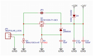
Schematic

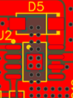
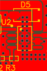
Top copper

Without zone

PS: the L3 coil is over dimensioned indeed.
Thanks in advance
Marco

-
Ask a related question
What is a related question?A related question is a question created from another question. When the related question is created, it will be automatically linked to the original question.