This thread has been locked.

If you have a related question, please click the "Ask a related question" button in the top right corner. The newly created question will be automatically linked to this question.

UCC28710: Device entering shutdown mode randomly

Part Number: UCC28710

Hi, 

We have a design based on PMP11185 using the UCC28710. It is targeted for 5V / 2A output to power a small BLDC inverter. Our power supply design is almost identical to PMP11185, including the Wurth transformer.

We notice that randomly we loose our 5V output for a few milliseconds, which of-course causes a reset in the inverter. We don't think the issue is noise or layout, as we have had previous generations of the UCC28710 device with 5V/1A running fine.

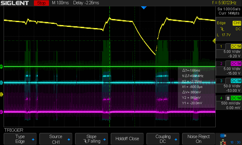
The image below shows the yellow trace which is VDD (pin 1 of UCC28170). At about 1.5ms it fires out one pulse to the FET and then enters shutdown, and re-starts when VDD is below 8.7V. VDD has a 1uF cap on it and it is clearly entering shutdown mode, allowing VDD to decay to 8.7V before restarting.

The other channels are Green (CS), Blue (VAux Winding), Purple (VS)

We have checked almost every condition that we can think of to determine why a fault occurs in the UCC28710.

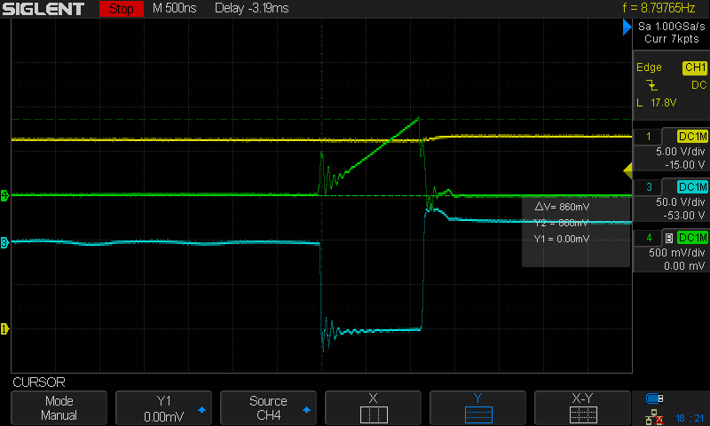
For example, the image below shows Green (CS), Blue (Aux Winding), Yellow (VDD) and we note that there is little noise on the CS line, no spikes and little ringing.

We have varied many parameters, including the size of the VDD capacitor (currently 1uF) up to 10uF as well as the VS resistor pairs. We have small 4.7pF caps on CS and VS pins (incase there was any noise).

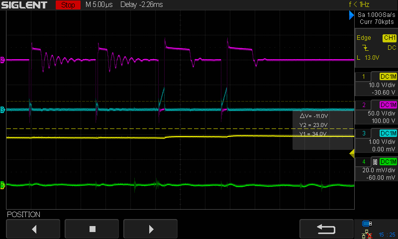
We have followed in detail SLUA783.pdf and checked almost everything we can, for example the case below shows purple (VS) and Blue (CS) lines and we feel that we are not viloating conditions like the skipped valley and our T_on value is low.

The image below shows Purple (VAux), Blue (CS), Yellow (VDD), Green is the current being sourced from the 5V rail.

The only possible condition we see here is that we might violate SLUA783 clause 6.2 "Very quick resonant decay with TVS Snubber". In the purple trace below (VAux) there is a small blip that aligns with Clause 6.2, but that should be very insignificant.

Can anyone from TI help out and possibly suggest why the device randomly enters shutdown mode and then restarts. We know there has to be a reason (for example some EMI or inverter noise suddenly aligning with a sampling window), but otherwise we are at a loss to determine.

Any help or ideas or things we can check would be great. We are happy to take more detailed scope captures of specific test cases if that can also help.

Thanks!

  • Hi,

    Thank you for reaching out.

    1. I think 1uF seems less on the Vdd pin. But as you have already tried increasing this to 10uF was there any difference in the hold up operation between the two cases. You can place a 47uF to see if this helps the case.

    2. It is seems from "DC1m" there is 1 Mhz bandwidth on the probe setting for AUX and CS pin signals. It is recommended to keep the probe at full bandwidth where noise effects can be seen.

    3. 4.7pf on CS and Vs should be ok. CS pin delay can be as high as 100ns also. Vs pin is recommended to be as low cap as possible (less tan 10pf).

    4. I partially agree the slow clamp diode as shown in the results of the app note section 6.2 not  affecting this. I think the issue could wrt noise on the Vs pin when inverter is working. One thing to check would be the Fsw at point of shutdown, an Fsw greater than max. supported by IC, then there could be problem of instability due to Vs driving the controller into OVP. 

    5. Also you could try checking the operation with and without inverter (wit just resistor load) connecte.

    Regards,

    Harish

  • Thankyou Harish,

    1. We note the datasheet for UCC28710 says max of 1uF for the VDD cap, we tried 10uF, we'll need to consider 47uF. I think the UCC28710 device is discharging the VDD cap during shutdown, and it is not a situation where the VDD Cap is too small for our appliation. When we fit 1uF, the decay and restart occurs in a few milliseconds, when we fit the 10uF cap, the decay and restart takes 500ms.

    2. Apologies for the poor images, the Bandwidth limit is only on our current clamp probe (green), not the signal probes.

    4. The best can can caputre before the shutdown event is three pulses on the Aux winding spaced at about 13uS, gives us 77KHz Fsw.

    5. The device exhibits this issue when it is connected to the inverter, a resistive load does not show this issue.

    Today we will focus on the Vs pin and take some detailed measurements as best we can.

    Thanks again for your support.

    Stomp!

  • Hi Stomp. Harish is out of office for the remainder of the week, but I will monitor this post in case you need support before he returns.

    Regards,

    Ray

  • Thanks Harish (and Ray),

    there could be problem of instability due to Vs driving the controller into OVP

    After some investigation we had a track on our PCB between Rs1 and Rs2 which was most likely the exact tuned length to pick up noise from the HV DC bus to our inverter. 

    While the design looked OK during operation, we suspect that the inverter noise was being coupled into VS and would randomly cause the UCC28710 device to immediately shut down.

    The fix was a small change to change the track geometery, and operation seems flawless now.

    Thanks.

  • Hi,

    Thank you for letting us know. Good to know that your issue is resolved.

    Regards,

    Harish