This thread has been locked.

If you have a related question, please click the "Ask a related question" button in the top right corner. The newly created question will be automatically linked to this question.

UCC27531EVM-184: UCC27531EVM-184

Part Number: UCC27531EVM-184
Other Parts Discussed in Thread: UCC27531

By measuring the voltage of J6 and J12, it is found that 4pcs out of 6pcs are -5.5V. Could you please check the reason
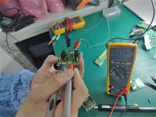
  for this, thank you

  • Hello,

    From the picture you provided, I see that J1 is shorted. The jumper installed on J1 is an out-of-box feature, and it shorts the 12V input for both isolated power supplies, where one supply outputs ~9V to "+VDR" node (referenced to -VDR), and the other outputs ~5V to "EMITTER" node (referenced to -VDR). This feature was done to support IGBT gate driving, which allows for the gate to swing between -4.75V to 17.25V. Section 2.4 of the user guide explains this.

    Since you did not put an input on PWM, The UCC27531 device will correctly output 0V when measured between the GATE and GND (-VDR). However, there's still ~5V on the EMITTER node, so measuring between GATE and EMITTER (J6 and J12) will yield about -5V, which is what you measured.

    For the other 2pcs, can you please verify what voltage you measured between J6 and J12? Can you also verify if J1 is shorted, C5 is a capacitor and not a resistor, and R5 is unpopulated on those pieces?

    Thanks,
    Rubas

  • Hello,

    Just following up to see if you still need assistance. I'd be happy to continue helping, or you could click the resolved button to close the thread.

    Thanks,
    Rubas