This thread has been locked.

If you have a related question, please click the "Ask a related question" button in the top right corner. The newly created question will be automatically linked to this question.

TPS25750: Which tool do you use to create firmware file for TPS25750?

Part Number: TPS25750
Other Parts Discussed in Thread: , TPS25751

I use the linux driver (Linux V6.8) at the following link:
<root>/drivers/usb/typec/tipd
It supports TPS25750.

From the following dmesg log, I think the driver is working. The problem is that there is no firmware file or the firmware file is not in the correct format.

root@rs802-reader:~# dmesg | grep tps
[ 6.969743] tps6598x 1-0021: GPIO lookup for consumer reset
[ 6.969761] tps6598x 1-0021: using device tree for GPIO lookup
[ 6.969813] tps6598x 1-0021: using lookup tables for GPIO lookup
[ 6.969818] tps6598x 1-0021: No GPIO consumer reset found
[ 8.558088] tps6598x 1-0021: tps25750_complete_patch_process: failed device patch complete status: 64

Please tell me which tool to use to create the firmware file?

  • Hi ,

    Thanks for reaching out. 

    Chris has been assigned this thread and will be helping you with it.

    Thanks ,

    Shubha

  • Hi Thinh,

    Unfortunately we do not directly support the Linux Drivers as they are not developed by TI, so I may not be able to support you with driver specific questions.

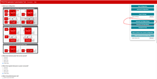
    In regards to "the firmware file", we have an online GUI that is available through the product page. 

    The GUI can be used to answer a questionnaire about the system, and then generate a binary or .C file that needs to be loaded the the TPS25750 on boot. This can either be done by loading the full flash binary to an I2C Flash that is attached to the I2Cc lines of the TPS25750, or by providing the .C file to an MCU to load over I2C.

    Thanks and Regards,

    Chris

  • Hi Chris,

    I succeeded in using the above method to create a firmware file for the driver. The log in the driver shows this:

    [ 7.323612] tps6598x 1-0021: GPIO lookup for consumer reset
    [ 7.323630] tps6598x 1-0021: using device tree for GPIO lookup
    [ 7.323681] tps6598x 1-0021: using lookup tables for GPIO lookup
    [ 7.323686] tps6598x 1-0021: No GPIO consumer reset found
    [ 9.474426] tps6598x 1-0021: controller switched to "APP" mode

    But I encountered another problem: when successfully loading the bin file created by the tool "TPS25750 Application Customization Tool", the system was reset due to power failure. I only powered the board via USB type C using a 20W power supply and noticed the power LED blinking abnormally. When the LED flashes once, the whole system is rebooted. it only happens when the bin file is successfully loaded.

    I also attached my setting that exported by "TPS25750 Application Customization Tool", Please help to check if any incorrect answer in the questionnaire 

    https://drive.google.com/file/d/1QcXwFkE_TcF0HqMPtJHCc0tBerFTImMr/view?usp=drive_link

    Or tell me how the array in the bin file is organized so I can check it myself.

    Best Regards,

  • Hi Thinh,

    Is this a custom board or are you using a TPS25750EVM?

    If it is the EVM, can you specify which LED it is?

    What is your dead battery config?

    What do you mean by 20-W power supply? What are the voltage/current's advertised?

    Can you obtain a PD log using a PD analyzer of the failure?

    I don't see anything stand out from the .json you shared. Is the system drawing load on boot up or is this being tested at no load?

    Do you have any more information in addition to the LED flashing? What voltages are you seeing on VBUS and PPHV, could you capture a scope trace?


    A small note, if you are still early in design, we highly recommend switching to the TPS25751. See here.

    Thanks and Regards,

    Chris

  • Hi Chris,

    Let me answer your questions as follows:

    Is this a custom board or are you using a TPS25750EVM?

    => I use my custom board.

    If it is the EVM, can you specify which LED it is?

    => I use my custom board.

    What is your dead battery config?

    => The board does not have backup battery.

    What do you mean by 20-W power supply? What are the voltage/current's advertised?

    => I use a DELL charger adapter. The output is 5V-30A/15W |---| 9V-30A/270W |---| 15V-3A/45W |---| 20V-3.25A/65W. Sorry for my mistake, It is a 65W charger not 20W.

    Can you obtain a PD log using a PD analyzer of the failure?

    => I will try. What tools i need to install?

    I don't see anything stand out from the .json you shared. Is the system drawing load on boot up or is this being tested at no load?

    => The power output from the PD is used for CPU (iMX8), RAM, EMMC and SD card, along with some other passive components...

    Do you have any more information in addition to the LED flashing? What voltages are you seeing on VBUS and PPHV, could you capture a scope trace?

    => The LED is connected directly to the power source, when it has power the LED lights up. This LED is on a custom board. 

    VBUS=19.86V , PPHV=19.86V

  • Hi Chris,

    I also don't know what to do, so the information I provide may not be useful or accurate. Now I want to determine whether I created the configuration file by the TPS25750 Application Customization Tool correctly or not?

    Can I load this configuration file into TPS25750EMV and compare the results?

  • Hi Thinh

    What is your dead battery config?

    => The board does not have backup battery.

    By this, I meant to ask what is your ADCIN1/2 divider set to?

    => I will try. What tools i need to install?

    You would need to obtain a PD analyzer or already have one. It is a USB-C CC line sniffer that you would put in series between the USB-C port and cable and it would report the messaging. There are some online, but the one we typically recommend recently got discontinued.

    => The power output from the PD is used for CPU (iMX8), RAM, EMMC and SD card, along with some other passive components..

    This doesn't seem to significant? Nothing in the 2-3+ A range? If not, you should be fine.

    => The LED is connected directly to the power source, when it has power the LED lights up. This LED is on a custom board. 

    VBUS=19.86V , PPHV=19.86V

    Does it light up at 5-V? Any voltage on VBUS?

    Can I load this configuration file into TPS25750EMV and compare the results?

    Yeah! That should be good. When you do this, could you measure the VBUS and PPHV pins on an Oscope and share what you find?

    Thanks and Regards,

    Chris

  • Hi Chris,

    I take a screenshot of the schematic and upload it to the google drive. Please take a look.

    ADCIN1 / ADCIN2 divider set to Always Enable Sink.

    I did further debugging and noticed the following:

    In the driver there is a code clear dead battery flag.

    /*
     * The dead battery flag may be triggered when the controller
     * port is connected to a device that can source power and
     * attempts to power up both the controller and the board it is on.
     * To restore controller functionality, it is necessary to clear
     * this flag
     */
    if (status & TPS_BOOT_STATUS_DEAD_BATTERY_FLAG) {
    	ret = tps6598x_exec_cmd(tps, "DBfg", 0, NULL, 0, NULL);
    	if (ret) {
    		dev_err(tps->dev, "failed to clear dead battery %d\n", ret);
    		return ret;
    	}
    }


    When I disable this code, the power loss phenomenon does not occur as I described above. But when measuring the voltage at the PPHV/PPHV1/PPHV2 pin, it was not as expected, I expected it to be 19V. and VBUS is 5V. The power supply 5V LED indicator is light up.

    When I enable this code, the power loss phenomenon does occur as I described above. when measuring the voltage at the PPHV/PPHV1/PPHV2 pins, it was as expected, I expected it to be 19V.  and VBUS is 19V. The power supply 5V LED indicator  is light up for about a second then off. The system rebooted and the process kept repeating.

    Does the process of clearing dead battery flag cause the PD to change PD Controller 's power input source? This causes the board to lose power?

  • Hi Thinh,

    The link to the google drive did not work for me.

    Does the process of clearing dead battery flag cause the PD to change PD Controller 's power input source? This causes the board to lose power?

    If you are taking system power from the USB-C port, it will boot in the "Dead Battery Configuration" set by the ADCIN dividers. If loaded in this way, it sets a "Dead battery flag" that indicates where it gets power from as well as prevents the port from sourcing high voltages. After it loads, it will attempt to load the binary image from an I2C flash or I2C host. Once the binary is loaded, the PD controller should run according to the App Config image (the settings set with the GUI) loaded with the binary image.

    The DBFg command clears the dead battery flag. You can read more about the command in the TPS25750 TRM

    When I disable this code, the power loss phenomenon does not occur as I described above. But when measuring the voltage at the PPHV/PPHV1/PPHV2 pin, it was not as expected, I expected it to be 19V. and VBUS is 5V. The power supply 5V LED indicator is light up.

    Are you still loading the binary image to the PD controller? Can you share the .json file that holds the App Config you used with the GUI?

    Questions:

    1. Can you explain how your system boots and loads the binary? As well as if any other commands are sent and when they are sent.

    2. When VBUS is stuck at 5-V, can you read the Status Register(0x1A), the Power Path Status Register (x026), and the Boot Status Register(0x2D)? Those may provide some information to help understand why the PD controller is only sinking 5-V.

    Thanks and Regards,

    Chris