This thread has been locked.

If you have a related question, please click the "Ask a related question" button in the top right corner. The newly created question will be automatically linked to this question.

TPS25750: TPS25750 + CAT24C256 + BQ25792 Working flow

Part Number: TPS25750
Other Parts Discussed in Thread: BQ25792, TPS25751

Dear TI,

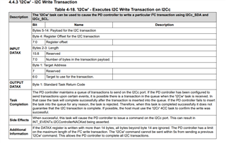
In current project I used TPS25750 as USC-C PD host and external EEPROM CAT24C256 for storing data configure from "TPS25750 Application Customization Tool".

After answering some question I got .c configure file and was able to flash it into eeprom and BQ25792 also negotiated expected voltage and current.

From my understanding that TPS25750 ack as I2C master to drive BQ25792 with configuration flashed on CAT24C256.

So do I really need to do and further control through i2c registers of BQ25792 directly or it all driven from TPS25750 side?

And how was the frequency TPS25750 configure BQ25792, from only start up or some interval? What if after start up, I directly control BQ25792 by its register, will it causing conflict or something?

Thanks!

Thi

  • Hi Thi, 

    Thank you for reaching out!

    The TPS25750 controls the registers on the BQ25792 needed to negotiate expected voltages and currents. If your system requires additional configuration, then you would need to control the battery charger via MCU for example. 

    The TPS25750 writes to the battery charger upon power up and also before a source/sink contract is negotiated. I recommend capturing an I2C log to gain a better understanding of the timings.

    I do also want to highlight the TPS25751. Please see the following E2E: https://e2e.ti.com/support/power-management-group/power-management/f/power-management-forum/1346998/faq-tps25751-migrating-from-the-tps25750-to-the-tps25751

    Best Regards, 

    Aya Khedr 

  • Hi Aya,

    Thank you for your reply!

    You mentioned "TPS25750 controls the registers on the BQ25792 needed", do we have listed of register configured by TPS25750?

    I just want to avoid conflict when I configure my own settings and the one TPS25750 handles.

    Thanks!

    Thi

  • Hi Thi, 

    I will put together a list of the registers we configure and get back to you with that by Friday. 

    Best Regards, 

    Aya Khedr 

  • Hi Aya,

    Could you please let me know any update on this request?

    Thanks!

    Thi

  • Hi Thi, 

    Please see below:

    1- Upon power up, the TPS25751 configures the BQ25792 to do the following:

    • Disable watchdog timer: Reg0x10
    • Disable OTG mode : Reg0x12 
    • Set the following parameters according to the user input in the GUI questionnaire:
      • Precharge Current: Reg0x08
      • Charge Termination Current: Reg0x09
      • Charge Voltage Limit: Reg0x01
      • Charge Current Limit: Reg0x03

    2- When the PD controller is in a sourcing state, the TPS25751 configures the BQ25792 to: 

    • Enable OTG Mode (Reverse Mode control) : Reg0x12
    • Reverse Mode System Voltage Limit according to the Voltages set in the Source PDOs in Transmit Source Capabilities (Reg0x32 on PD): Reg0x0B
    • Reverse Mode Input Current Limit according to the currents set in the Source PDOs in Transmit Source Capabilities (Reg0x32 on PD): Reg0x0D

    3- When the PD controller in a sinking state, the TPS25751 configures the BQ25792 to:

    • Set the following parameters according to the user input in the GUI questionnaire:
      • Precharge Current: Reg0x08
      • Charge Termination Current: Reg0x09
      • Charge Voltage Limit: Reg0x01
      • Charge Current Limit: Reg0x03
      • VIINDPM: Reg0x05
      • IINDPM: Reg0x06
    • Enable forward mode for charging a battery: Reg0x0f

    4- During voltage transitions, the PD configures the battery charger to safely discharge 

    5- Upon detach or hard reset, the PD configures the battery charger to disable forward/reverse mode 

    In general, there should not be a need to do further control as the necessary control is driven from the PD controller. Just to clarify, if your system requires further control of the battery charger, the MCU would need to write to the battery charger through the PD controller using a 4CC command 'I2Cw' (see below from TPS25751 Technical Reference Manual). The team is working on an application note detailing how to utilize this command and will be released in the near future. In the meantime, feel free to reach out with any questions/concerns!

    Best Regards, 

    Aya Khedr 

  • Hi Aya,

    Thanks for you reply!

    I am using TPS25750, hope your above explanation also correct for TPS25750?

    Thanks!

    Thi

  • Hi Thi, 

    We are recommending all new designs to use the TPS25751 instead of the TPS25750. The TPS25751 improves the I2C functionality for the supported battery chargers, specifically the implementation in the flow described above. 

    Please let me know if you have any questions/concerns. 

    Best Regards, 

    Aya Khedr 

  • TPS25751 instead of the TPS25750--are they pin to pin compatible and reg to reg compatible?


  • Hi Thi, 

    Yes, the TPS25751 is pin-to-pin compatible with the TPS25750. It is also register-register compatible. The TPS25751 has additional features/registers, but any implementation made with the TPS25750 will remain the same when ported into the TPS25751. 

    Best Regards, 

    Aya Khedr