This thread has been locked.

If you have a related question, please click the "Ask a related question" button in the top right corner. The newly created question will be automatically linked to this question.

LM5152-Q1: LM5152QRGRRQ1 Config mode, clock and duty

Part Number: LM5152-Q1

Hello

I would like to ask three questions regarding the specifications of the LM5152-Q1.

Q1.

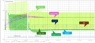
Please tell me about the configuration mode of LM5152-Q1.

I checked the input voltage, output voltage, high-side and low-side gate terminal voltage, etc.

in config mode with pspice for TI when there is no load.

There is a description of configuration in chapter 9.3 of the datasheet.

I didn't understand the load conditions.

Is it the same for high load and no load?

If it's not common, do you have the data sheet for no load or high load?

If there is no description of high load, please provide details.

Q2.
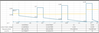
When operating with an input voltage of 6.5V, an output voltage of 12.5V, and a constant current load of 9A,

the SW frequency of the high-side and low-side gate voltages did not reach the set value of 488.8kHz.
There are times when it becomes 465kHz, 526kHz, 571kHz.

Can the frequency change like this? I would like to know the reason for this.
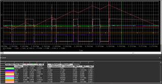

Q3.
Are there any restrictions on DUTY value?

red :sense current

pink:High side gate voltage

violet:Lo side gate voltage

green:VOUT


Best regards,

takahashi

  • Hello Takahashi,

    Thanks for reaching out to us via e2e.

    Q1
    There is no such thing as a configuration mode.
    There is a configuration time during which the device is reading the configuration / mode settings from the external pins.
    This time elapses BEFORE the device starts switching. Also, the SS pin voltage should be close to GND during that time.
    So, what you call "Configuration Mode" in your first image has nothing to do with the configuration time, because the device is switching, and also the SS pin voltage is already sitting at around 3V.

    Q2
    The switching frequency itself is not changing.
    But, dependent on the output power requirements, the device may ship some cycles (both FETs are OFF when a cycle is skipped).
    The frequency therefore appears as if it was lower.

    Q3
    The maximum duty cycle depends on the switching frequency.
    See table on page 10 - Pulse Width Modulation (PWM)

    Best regards
    Harry