This thread has been locked.

If you have a related question, please click the "Ask a related question" button in the top right corner. The newly created question will be automatically linked to this question.

TPS65987DDK: Stand-alone or not ? Main power rail ?

Part Number: TPS65987DDK
Other Parts Discussed in Thread: TPS65987DDJ, TPS65988

Hello, 

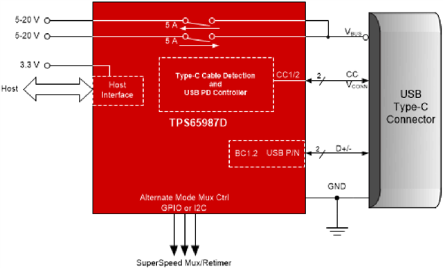
I need to supply 45W (15v x 3A) to an external eGPU using a USB PD interface from a Power board. 

The power board shall source 45W through a Type-C connector and cable till the external eGPU.using the USB PD interface. 

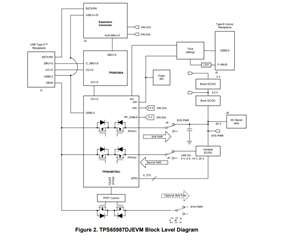
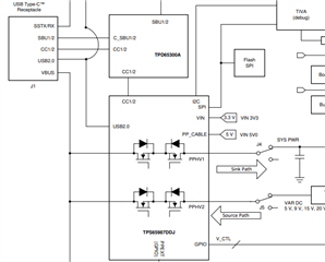
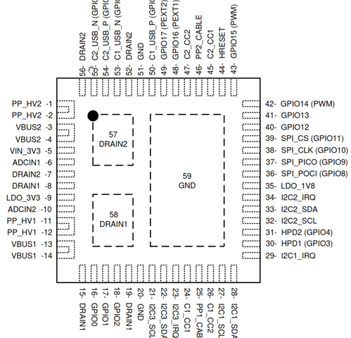
In order to implement that I chose the TPS65987DDK PD controller  which according to the datasheet can source up to 20v/5A and work in stand-alone mode. 

My questions are :

1. How does it work in stand-alone mode ? It is not clear from datasheet. Datasheet only introduces typical implementations where a an external DMC controls it and even boot it using I2C protocol. 

How can it work independently in stand-lone mode in which boot is done automatically from an EEPROM with no any controller ? Can you please share a "typical application" example of that ? 

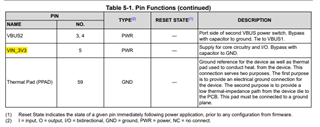
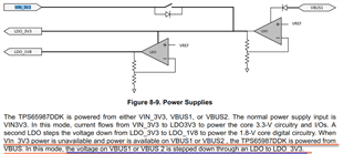
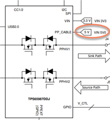
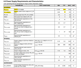
2. Does PPHV=15v connection is enough to power that PD controller ? Or additional 3.3v supply is a must ? 

Thanks in advance, 

Ohad (HW engineer - (GE-healthcare). 

  • Hi Ohad, 

    Thank you for reaching out!

    I will look into this further and get back to you by Thursday. 

    Best Regards, 

    Aya Khedr 

  • Hello Aya, 

    Is there any comment regard my questions ? 

    BR, 

    Ohad

  • Hi Ohad, 

    Thank you for your patience. Please see my comments below: 

    1. Originally, the TPS65987DK was intended only for applications following thunderbolt reference designs. The typical application schematic in the datasheet is a an example of a docking application in which a Dock Management Controller (DMC) is utilized. We are increasing the scope of the TPS65987DK to non thunderbolt systems as well. 

    In general, our PD controllers are standalone solutions in that the power path, PD controller, and PD Phy are all included in a single chip solution. Our Evaluation Module would be a good example showcasing the use of an EEPROM (see SPI Flash in block diagram below). For schematics, please see section 4 in the TPS65987DJ Evaluation Module User Guide

    2. A 3.3V supply is needed for core circuitry and I/O. 

    Please let me know if you have additional questions/concerns. 

    Best Regards, 

    Aya Khedr 

  • Hi Aya, 

    Regard question 1 : On the one hand you claim that your PD controllers are standalone solutions and you recommend the EVM as an example : 

    In general, our PD controllers are standalone solutions in that the power path, PD controller, and PD Phy are all included in a single chip solution. Our Evaluation Module would be a good example showcasing the use of an EEPROM

    And on the other hand, as seen in the EVM, the chip TPS65987DDJ is not standalone and dependent on TPD65300A for communicating the CC : 

    Regard question 2 : 

    The fact that 3.3v is needed inside the chip for the internal circuits is clear. The reason I asked if 3.3v supply is must since it is written in the datasheet that the device knows to generate 3.3v from VBUS input power when if VIN_3V3 is not  connected : 

    In that case, I would like to know what would be the efficiency since if VBUS=15v and an internal LDO generates from it 3.3v than it seems quite a lot heat dissipation inside the chip. What is the current limitation on the 3.3v in that case ? 

    And another question - where does the 5v for USB base connection comes from ? Does it need to be supplied externally as seems in the EVM block diagram ? 

    Or is it generated internally in the chip form VBUS voltage which can be up to 20v  ?  

    According to datasheet, it doesn't seem there is a special input for 5v in the pinouts. There is only PPHV1/2 that can be up to 20v : 


  • Hi Ohad, 

    1- The TPD6S300A is a USB Type-C port protection device that provides 20-V Short-to-VBUS overvoltage and IEC ESD protection. The PD controller does not rely on this device for communication on the CC lines. 

    2-  The TPS65987DDK supports booting from no-battery or dead-battery conditions by receiving power from VBUS (this would be the case where VIN3V3 is not present as described below).  

    3- PP_Cable is the input to power VCONN output on C_CC pins. VCONN is provided by the source to power cables with electronics in the plug. Please see below from the USB Type-C specification on when VCONN is required (this may or may not be applicable to your design)

    Could you provide more insight on your design? Do you require the support of any alternate modes, such as DisplayPort? 

    Best Regards, 

    Aya Khedr 

  • Hi Aya, 

    Thanks for the information. 

    So in general I understand from you that regard my questions: 

    1. TPD6S300A is not a MUST for working with TPS65987DK. 

    2. 3.3v is mainly recommended to have a separate supply on the PCB and not be dependent on VBUS like in Dead battery (My application doesn't rely on battery). 

    3. Still not understood - Where exactly does the 5v USB supply come from ? Is it generated from VBUS or shall it be supplied separately just like the 3.3v? 

    Regard my application I have given details in my first message you can read it again. I only need here to source power using USB PD Type C to an external eGPU and I emphasize again - My side is the source so in general my side shall supply the power to an eGPU. 

    Considering that, I ask again, how does the 5v for based USB communication is being supplied ? 

    Thanks, 

    Ohad 

  • Hi Ohad, 

    1. Yes, that is correct. 

    2. The core digital circuitry is powered up from VIN3V3, and is required. The only scenario in which the device is powered from VBUS, is in dead-battery mode, which is not applicable in your design from my understanding. 

    3. The 5V supply is supplied externally similar to the 3.3V. 

    Best Regards, 

    Aya Khedr 

  • Hi Aya, 

    Regard 3 - That is not mentioned anywhere in the data-sheet. Not in the power management, not in the pinout configuration: 

    and even not in the simplified schematic: 

    The only power inputs mentioned are PPHV1 and PPHV2 which are both can be up to 20v. Ni specific 5v input is mentioned. 

    On what are you based on when telling 5v input is required? 

    BR, 

    Ohad

  • Hi Ohad, 

    Just to clarify, the 5-V input (PP_CABLE) is only required if your system needs to source VCONN to power cables with electronics in the plug (this is typically required when the current capability>3A). This is not needed for all systems. 

    See Section 6.5 Power Supply Requirements and Characteristics below: 

    Best Regards, 

    Aya Khedr 

  • Hi Aya, 

    So just to make sure, the only source supply that can be for VCONN is a separated external supply of 5v ? 

    I saw this in datasheet, what does it exactly mean ? Isn't that say 5v can also be achieved internally from VBUS ? If yes than, can it support VCONN ? 

    Thanks, 

    Ohad

  • Hi Ohad, 

    So just to make sure, the only source supply that can be for VCONN is a separated external supply of 5v ? 

    Yes, that is correct. 

    I saw this in datasheet, what does it exactly mean ? Isn't that say 5v can also be achieved internally from VBUS ? If yes than, can it support VCONN ? 

    This is separate to the VCONN discussion. VBUS transition to VSAFE5V is referring to the PD negotiated voltage transitions (For example, 20V --> 5V), and is detailed in the USB Type C specification. 

    Best Regards, 

    Aya Khedr 

  • Hi Aya, 

    I have found mismatch in datasheet regard 3 pins in datasheet, They are defined differently in two pages: 


    Name (In Page 3)

    Name (In Page 4)

    Pin Number

    GND

    C2_CC1

    45

    GND

    PP2_CABLE

    46

    GND

    C2_CC2

    47

    Please tell which is the right pin naming ? 

    Ohad

  • Hi Ohad, 

    Figure 5-1 on page 3 is imported from the TPS65988 datasheet (dual-port device). We are working on updating the pinout naming in the TPS65987DK datasheet. 

    For the TPS65987DK, please use the naming and pin functions that are stated in Table 5-1. 

    Best Regards, 

    Aya Khedr 

  • Hi Aya, 

    Could you please explain, what are the D+/D- used for in the device? I saw in the first page they are connected while as far as I know, Power delivery messages are transferred only through the CC lines. In datasheet it is written that they support BC1.2, can you explain what is it ? Why D+/D- shall be connected to that device ? 

    Ohad

  • Hi Aya, 

    BTY, 

    How does it turn up ? Shall it be connected through one of its I2C or SPI to an EEPROM where its SW is loaded from when power up ? 

    Ohad

  • Hi Ohad, 

    Please post a new E2E thread with a descriptive title for better trackability. Thank you!

    Best Regards, 

    Aya Khedr