


Hello, please help confirm some questions about TPS929240
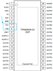
Q1: If we do not plan to use the Fail-safe function of the chip, how to deal with the FS1 and FS0 pins, can they be suspended or directly grounded;
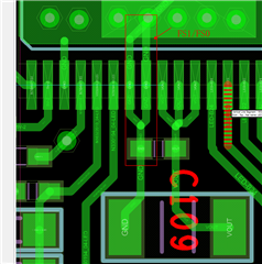
Q2: To connect the above question, suppose if I ground FS1 and FS0, I find that when doing PCB layout, can the capacitor of SUPPLY be grounded to the nearby FS1 or FS0 pin, as shown in the following figure, is this going to be a problem internally,
Q3: If I don't use the ERR pin, can I leave this pin floating?
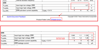
Q4: The following figure shows the level range of 929120 and 929240ERR pins. What is the consideration of changing the level range from 0.7V 2V of 929120 to 1.1V 1.2V of 929240, because the parameters of this block are close to the fault pin parameters of TPS9263/TPS92611, cascading can be done directly,
Q5:ERR pull-up resistor is less than 10K. If I use 1K resistor and pull-up is 5V, if IPD(ERR) current is pressed 3mA at this time, the ERR pin voltage is 2V. If the in Fail-safe States and individual channels Fail, even if OFAF = 1 is set on the chip, will other channels not be shut down?
