Other Parts Discussed in Thread: BQ25302, TPS63806, TPS22995
Hi team,
This issue extends from previous issue.


Description
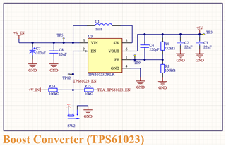
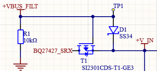
I have decided to add a new power supply IC(TPS61023) dedicated to supplying power to piezoelectric devices that periodically draw a significant amount of current. I would like to invite you to assist in reviewing the following schematic of the TPS61023 (outputting 5V) to see if there are any issues. This switch-mode power supply will be connected to a BOS1901, a driver IC for piezoelectric actuators, which will draw a periodic current (expected Ipeak is about 2400 mA, @300 Hz sine wave). There are two possible sources for Vin: one is VBUS 5V3A, and the other is a Lipo battery. Could you advise if the design of this schematic is reasonable?
Question
1. Additionally, as stated in chapter 9 of the TPS61023 datasheet, a larger electrolytic capacitor (e.g., 100 uF) may be required to maintain stability when the power source is located further away. However, I understand that the capacitance for USB devices should typically not exceed 10 uF. Thus, my question is, if the USB cable is longer than a few inches, would adding a bulk capacitor affect the USB bus power and potentially disrupt the enumeration of other devices on the bus? Is there an alternative solution?
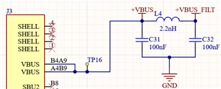
2. Another issue is that if I am using other ICs, and the total capacitance on the usb vbus could amount to 30 ~ 40uF (e.g., BQ25302 PMID 10uF, Vin 2.2uF; TPS63806 Vin 10uF, TPS61023 Vin 10uF, assuming bulk capacitor is not included; totaling 32.2 uF), which is much higher than the USB standard of 10uF. What can be done to resolve the capacitance issue from so many ICs to prevent the other devices on the USB bus from being reset?
I am very grateful for any suggestions and apologize for not fully considering the previous issue, which has led to the need to ask a follow-up question
Regards,
Dennis


