This thread has been locked.

If you have a related question, please click the "Ask a related question" button in the top right corner. The newly created question will be automatically linked to this question.

LM5025AEVAL:LM5025AEVAL circuit issues

Part Number: LM5025AEVAL

Hi,

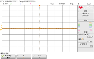
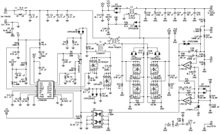
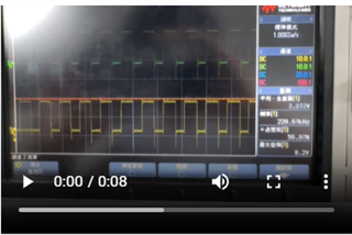
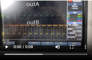
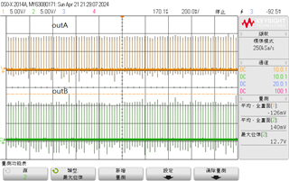
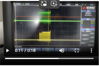
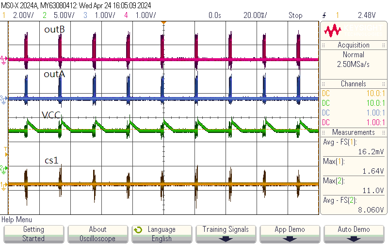
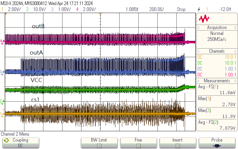
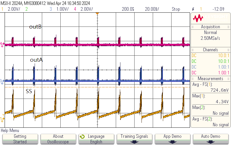
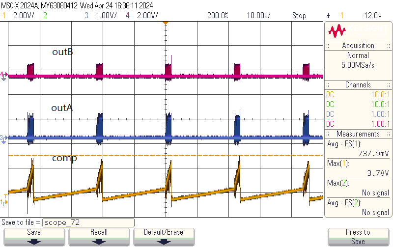
I built a circuit using the LM5025AEVAL, but the output voltage is only 1.3V, and the transformer makes a strange noise. What could be the possible reasons for these issues?

Thank you.

  • Hi,

    please provide your schematics for review. There should be something wrong on your design or your board. we need to review your schematics to find clues where wrong.

  • Hi,

    I followed the circuit described in the paper.

    www.ti.com.cn/.../snva097b.pdf

  • Hi,

    If that is the circuit you followed exactly, then you can measure each waveform to compare between yours and the EVM to trace where you see difference, starting with switching frequency, gate drive, Vds, etc. 

    Since you followed that circuit, then no need to review as the EVM works just fine. Your circuit does not work then there has to be something you did not build correctly you need to compare one circuit at a time to trace all then you can find where you got something wrong, then fix that, your board will work like the EVM.

  • ch1 is out_A, and ch2 is out_B.

    From the waveform, it appears very unstable, and the output voltage is also incorrect. I have replaced many components but still can't identify the problem.

    thanks for your reply.

  • Hi,

    In your video, please label each waveform.

  • Hi,

    The show is normal, but something trigger to turn off both. What was the horizontal scale? Can you use horizontal scale 200ms/div to retake the waveforms so we can see what happened?

  • thanks for your reply.

  • Hi,

    I think still using video but with 200ms /div that way to show the waveform up and down 

  • This is a video from 200ms to 2us.

    thanks for your reply.

  • Hi,

    What was the input voltage and the load current?

    In this below, both OUTA and OUTB off. You need to find what caused both of them off. VCC, CS1, SS, COMP, etc. Capture each of these along with OUTA and OUTB off and on to see any of them not in the correct range, or trigger protection.

  • Input voltage 36V, no load.

    I am not sure if this is caused by CS1.

    thanks for your reply.

  • Hi,

    It looks CS2 threshold was triggered as soft start present.

    Note CS2 (and CS1) threshold is only 0.25V. The waveform shows CS1 much higher than 0.25V. You need to reduce the current sense noise to resolve this issue as first step.

  • Do you mean that I should first improve the layout?

  • Hi,

    You need to find a way to make CS1 and CS2 peak < 0.25V, no matter what you do, to avoid the false over current protection triggered.