Other Parts Discussed in Thread: TPSI3052-Q1,
Hi, apologies if any of my questions have been answered previously but I couldn't see any direct links.
I'd like to drive 3x FETs to short the phases of a BLDC with the TPSI3050. The combined gate capacitance of all three is 12nF and combined gate charge is ~120nC (at the TPSI3050 10V drive voltage). They will be controlled via duty cycle of a 1kHz PWM and I would expect to see currents up to 25Apk-pk through the motor when braking the FETs fully ON.
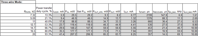
First off does this sound reasonable? Using a basic t=CV/I calc, can I estimate that the rise time (based on the TPSI peak drive current of 1.5A) will be ~12nF*10V/1.5A = ~80ns? (Best case most likely due to any losses in the circuit which might limit I) And that given a PWM of 1kHz (and thus a cycle time of 1ms), I should have plenty of time to recharge the VDDH/VDDM caps between each switch of the FETs? The calculator tool suggests that with Cdiv1, Cdiv2 = 500nF each, I would see 0.492V sag max on VDDH and that even at the lowest PXFR setting (7.32kR), the rail would still recover fully after 1.51.5us (allowing a max swithing speed of 6.6kHz). Am I interpreting all that correctly?
Is there any advantage of increasing the PXFR value then in this case? It's not going to give me any faster switching times right, it's just going to allow the circuit to recover more quickly?
Is there a reason why it drives 10V and not 5V? When FETs tend to have a Vgs(th) lower than 5? Is it to minimise Rds(on)? Does this increase risk of overshoot damaging say a FET with VGSMAX of +/-12V?
Also, this seems to be the only dedicated isolated gate driver with integrated isolated supply on the market and seems like a great solution for space constrained designs, any idea why all the other vendors require an external isolated supply?!
Many Thanks in advance,
Cheers,
Dave