This thread has been locked.

If you have a related question, please click the "Ask a related question" button in the top right corner. The newly created question will be automatically linked to this question.

TPS923654: Can TPS923654 be used for LED lighting with Vin=24V, Vout(Vf)=50V and Io=3.5A conditions?

Part Number: TPS923654
Other Parts Discussed in Thread: TPS923652, TPS922052, TPS92640

Hello guys,

One of my customers is considering using TPS923654 for their new products.

At this moment, they have the following questions.
Could you please give me your reply?

Q1.
Can TPS923654 be used for LED lighting with Vin=24V, Vout(Vf)=50V and Io=3.5A conditions as boost topology?

Q2.
Can TPS923654 be used for LED lighting with Vin=60V, Vout(Vf)=50V and Io=3.5A conditions as buck topology?

Q3. 
They want to calculate the inductor value for LED lighting system which can operate with the conditions in Q1 and Q2.
They know that it is possible to calculate it with equation 12 on page 17 of TPS923654 datasheet.
But they want to know how to determine fSW.
What frequency is general for fSW?
Is it 1.2MHz like a describing in datasheet?
Or lower?

Your reply would be much appreciated.

Best regards,
Kazuya.

  • Hi Kazuya,

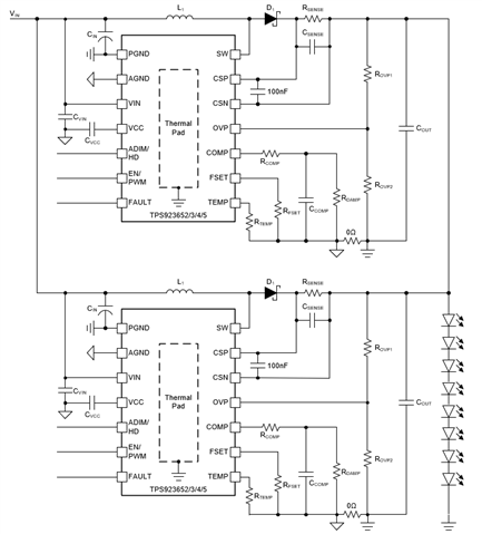
    For Q1, a single TPS923654 cannot be used for LED lighting with Vin=24V, Vout(Vf)=50V and Io=3.5A conditions due to switching FET cycle-by-cycle current limit. However, you can parallel two TPS923654 (each output 1.75A) to work for above IO condition. A graphical illustration is shown below to illustrate how to parallel two TPS923652/3/4/5 to achieve larger output current / higher output power capability. 

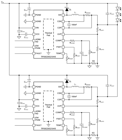
    For Q2, although TPS923654 can be used in buck-boost connection, Vin+Vf=60V+50V=110V is out of the recommended operating conditions (Please refer to Section 7.3 Recommended Operating Conditions and Section 9.2.2 from the datasheet). You should use a Buck LED driver for this application, for example TPS92640/1 or TPS922052/3/4/5. One TPS92640/1 can handle output power of Vout(Vf)=50V and Io=3.5A. You may need to parallel two TPS922052/3 to achieve an output power of Vout(Vf)=50V and Io=3.5A due to thermal limit. (TPS92205x integrates the switching FET but TPS92640/1 does not.) A graphical illustration is shown below to illustrate how to parallel two TPS922052/3/4/5 to achieve larger output current / higher output power capability. 

    For Q3, the f_SW = 1.2MHz in Section 9.2.2 from the datasheet is just an example. There is no general rule for all. You should select f_SW based on actual working conditions and design requirements.

    Best Regards,

    Steven

  • Hi Steven,

    Thank you very much for your reply.

    I understood your answer 1 and 2.
    Could I ask you a few questions about answer 3?
    I understood that there is no general rule for switching frequency.
    I tried to calculate inductor value using equation 12 and described parameters on page 27 of TPS92365x datasheet for buck boost topology.
    (The parameters are  VIN(max) = 24 V, VOUT = 12 V, ILED = 2 A, fSW = 1.2 MHz, choose KIND = 0.5)

    I calculated as the below.

    L=(24V * 12V)/((12V + 24V) * 0.5 * 2A *1.2MHz))

      =288/((36 * 0.5 * 2 *1.2M)

      =288/43200000

      = about 6.7uH

    The datasheet says the answer is 4.4uH

    Could you please tell me which my mistake is?

    Also same things happened when I calculated inductor value using equation 2 and described parameters on page 22 for boost topology.
    (The parameters are  VIN(max) = 12 V, VOUT = 36 V, ILED = 1 A, fSW = 500 kHz, choose KIND = 0.6)

    I calculated as the below.

    L=(12V * (36V - 12V))/(36V * 0.6 * 1A * 500kHz)

      =288/10800000

      = about 267uH

    The datasheet says the answer is 8.9uH

    Could you please tell me which my mistake is?

    Thank you again and best regards,
    Kazuya.

  • Hi Kazuya,

    I am currently out of office. I will reply to you next Monday. Thanks for your understanding.

    Best Regards,

    Steven

  • Hi Kazuya,

    Please be noticed that for Equation (2) and Equation (12) from the datasheet, you should use I_L(max) but not I_LED(max) for calculation.

    For boost topology, you can calculate I_L(max) with I_L(max) = V_OUT * I_LED(max) / efficiency / V_IN.

    For buck-boost topology, you can calculate I_L(max) with I_L(max) = V_OUT * I_LED(max) / efficiency / V_IN + I_LED(max).

    Best Regards,

    Steven

  • Hi Steven,

    Thank you very much for your reply.
    I understood that I should use I_L(max) but not I_LED(max) for the calculation.
    Could I ask you an additional question as the below?

    What is the value of efficiency used for each I_L(max) calculation in the datasheet case?
    Is it 0.75?

    Thank you again and best regards,
    Kazuya.

  • Hi Kazuya,

    When you design the components at the first time, you can estimate a value for the efficiency (like 85%) and use that for calculation. You can later adjust the components based on your test results.

    Best Regards,

    Steven

  • Hi Steven,

    Thank you very much for your reply.

    I calculated IL(max) and L value using the equation you told me and equation 2 on datasheet. Also the efficiency=0.85.
    Datasheet conditions are the follows in case of boost topology.
    VIN(max) = 12 V, VOUT = 36 V, ILED = 1 A, fSW = 500 kHz, choose KIND = 0.6)

    Then 
    IL(max)=V_OUT * I_LED(max) / efficiency / V_IN.
                = (36V*1A)/0.85/12V
                = 3.592 A

    L=(VIN(max)*(VOUT-VIN(max))/(VOUT*Kind*IL(max_A)*fSW)
      = (12V*(36V-12V))/(36V*0.6*3.592*(500*1000))
      = 7,424 uH

    I think this 7.4uH is not near to 8.9 uH the device datasheet says.

    Which is not correct in my calculation?

    Your reply would be much appreciated.

    Thank you again and best regards,
    Kazuya. 

  • Hi Kazuya,

    The datasheet uses an ideal value = 100% for the efficiency to calculate the I_L(max) and this will give the calculated inductance of 8.9uH.

    Best Regards,

    Steven

  • Hi Steven,

    Thank you very much for your strong supports.

    I understood well!

    Thank you again and best regards,
    Kazuya.

  • Hi Kazuya,

    You are welcome. I am going to close this thread. Please feel free to contact me again if you have any further question.

    Best Regards,

    Steven