Hello,
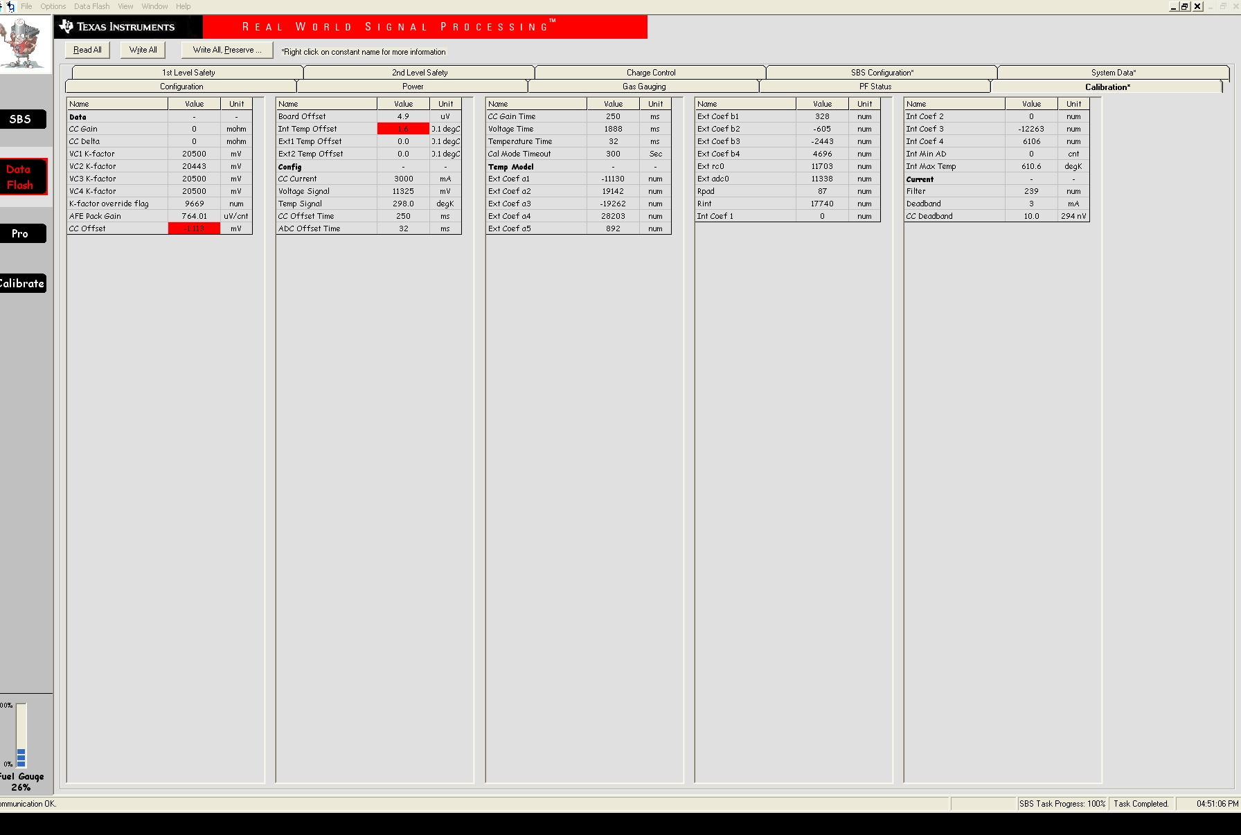
On our first batch of new batteries from our contract manufacturer we're finding nearly 100% have the "CC Gain" and "CC Delta" both set to 0. This does not correspond to our golden file. All other parameters match the golden file. We are unable to replicate it here.
We will be visiting to observe their procedure for programming and calibrating the batteries. In the meantime, do you have any ideas of how this might be happening?
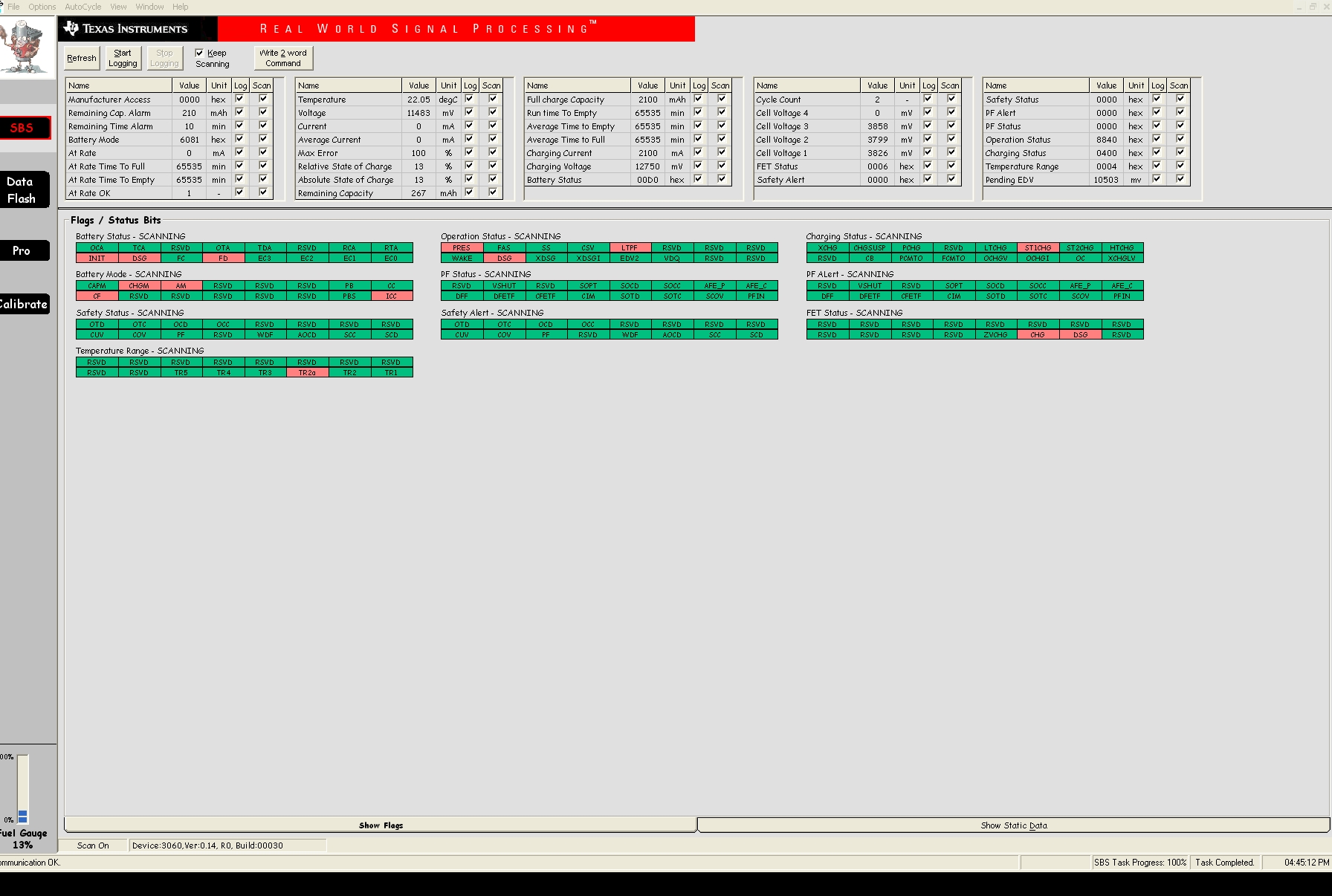
I have attached the .gg file (uploaded as .txt since the forum won't accept .gg) and relevant screenshots from the bqEVSW software.
Thanks for any help!
[Header]
bq EVSW Version = 0.9.59
DeviceName = bq3060 v0.14
Time = 9/16/2011 4:45:45 PM


[Voltage(1st Level Safety)]
LT COV Threshold = 4200
LT COV Recovery = 4100
ST COV Threshold = 4300
ST COV Recovery = 4200
HT COV Threshold = 4250
HT COV Recovery = 4150
CUV Threshold = 2800
CUV Recovery = 3000
[Current(1st Level Safety)]
OC (1st Tier) Chg = 2100
OC (1st Tier) Chg Time = 10
OC Chg Recovery = 200
OC (1st Tier) Dsg = 2100
OC (1st Tier) Dsg Time = 10
OC Dsg Recovery = 200
Current Recovery Time = 8
AFE OC Dsg = 0D
AFE OC Dsg Time = 00
AFE OC Dsg Recovery = 5
AFE SC Chg Cfg = 10
AFE SC Dsg Cfg = 10
AFE SC Recovery = 1
[Temperature(1st Level Safety)]
Over Temp Chg = 60.0
OT Chg Time = 2
OT Chg Recovery = 55.0
Over Temp Dsg = 60.0
OT Dsg Time = 2
OT Dsg Recovery = 55.0

[Voltage(2nd Level Safety)]
LT SOV Threshold = 4400
ST SOV Threshold = 4600
HT SOV Threshold = 4500
SOV Time = 2
PF SOV Fuse Blow Delay = 0
Cell Imbalance Current = 5
Cell Imbalance Fail Voltage = 1000
Cell Imbalance Time = 1
Battery Rest Time = 1800
Min CIM-check voltage = 3000
PFIN Detect Time = 0
[Current(2nd Level Safety)]
SOC Chg = 3000
SOC Chg Time = 0
SOC Dsg = 3000
SOC Dsg Time = 0
[Temperature(2nd Level Safety)]
SOT Chg = 65.0
SOT Chg Time = 5
SOT Dsg = 78.0
SOT Dsg Time = 5
Open Thermistor = -33.3
Open Time = 0
[FET Verification(2nd Level Safety)]
FET Fail Limit = 20
FET Fail Time = 2
[AFE Verification(2nd Level Safety)]
AFE Check Time = 5
AFE Fail Limit = 10
AFE Fail Recovery Time = 20
AFE Init Retry Limit = 6
AFE Init Limit = 20

[Charge Temperature Cfg(Charge Control)]
JT1 = 0.0
JT2 = 10.0
JT2a = 30.0
JT3 = 45.0
JT4 = 55.0
Temp Hys = 1.0
[Pre-Charge Cfg(Charge Control)]
Pre-chg Current = 100
Pre-chg Voltage = 2800
Recovery Voltage = 3100
[Charge Cfg(Charge Control)]
LT Chg Voltage = 12300
LT Chg Current1 = 525
LT Chg Current2 = 525
LT Chg Current3 = 525
ST1 Chg Voltage = 12750
ST1 Chg Current1 = 2100
ST1 Chg Current2 = 2100
ST1 Chg Current3 = 2100
ST2 Chg Voltage = 12750
ST2 Chg Current1 = 2100
ST2 Chg Current2 = 2100
ST2 Chg Current3 = 2100
HT Chg Voltage = 12600
HT Chg Current1 = 525
HT Chg Current2 = 525
HT Chg Current3 = 525
Cell Voltage Threshold1 = 3900
Cell Voltage Threshold2 = 4000
Cell Voltage Thresh Hys = 10
[Termination Cfg(Charge Control)]
Taper Current = 100
Taper Voltage = 300
Current Taper Window = 40
TCA Set % = -1
TCA Clear % = 95
FC Set % = -1
FC Clear % = 98
[Cell Balancing Cfg(Charge Control)]
Cell Balance Threshold = 3900
Cell Balance Window = 50
Cell Balance Min = 10
Cell Balance Interval = 20
[Charging Faults(Charge Control)]
Over Charging Voltage = 200
Over Charging Volt Time = 2
Over Charging Current = 200
Over Charging Curr Time = 2
Over Charging Curr Recov = 100
Depleted Voltage = 8250
Depleted Voltage Time = 2
Depleted Recovery = 9000
Over Charge Capacity = 210
Over Charge Recovery = 2
FC-MTO = 10800
PC-MTO = 3600
Charge Fault Cfg = 3F

[Data(SBS Configuration)]
Rem Cap Alarm = 210
Rem Energy Alarm = 2300
Rem Time Alarm = 10
Init Battery Mode = 0081
Design Voltage = 11100
Spec Info = 0031
Manuf Date = 01-Jan-1980
Ser. Num. = 0001
Cycle Count = 2
CC Threshold = 1890
CC % = 90
CF MaxError Limit = 100
Design Capacity = 2100
Design Energy = 23300
Full Charge Capacity = 2100
DOD at EDV2 = 15232
Manuf Name = Texas Inst.
Device Name = bq3060
Device Chemistry = LION
[Configuration(SBS Configuration)]
TDA Set % = 6
TDA Clear % = 8
FD Set % = 2
FD Clear % = 5
TDA Set Volt Threshold = 11250
TDA Set Volt Time = 5
TDA Clear Volt = 12375
FD Set Volt Threshold = 11250
FD Volt Time = 5
FD Clear Volt = 12375

[Manufacturer Data(System Data)]
Pack Lot Code = 0000
PCB Lot Code = 0000
Firmware Version = 0000
Hardware Revision = 0000
Cell Revision = 0000
[Manufacturer Info(System Data)]
Manuf. Info = 0123456789ABCDEF0123456789ABCDE
[Lifetime Data(System Data)]
Lifetime Max Temp = 31.6
Lifetime Min Temp = 19.0
Lifetime Max Cell Voltage = 4005
Lifetime Min Cell Voltage = 2789

[Registers(Configuration)]
Operation Cfg A = 0220
Operation Cfg B = 0DEE
Operation Cfg C = 0007
Permanent Fail Cfg = 0000
Non-Removable Cfg = 0000
[AFE(Configuration)]
AFE State_CTL = 10

[Power(Power)]
Flash Update OK Voltage = 9000
Shutdown Voltage = 7500
Shutdown Time = 10
Cell Shutdown Voltage = 2500
Cell Shutdown Time = 10
AFE Shutdown Voltage = 3000
Sleep Current = 10
Bus Low Time = 5
Cal Inhibit Temp Low = 5.0
Cal Inhibit Temp High = 45.0
Sleep Voltage Time = 5
Sleep Current Time = 20
Wake Current Reg = 00

[CEDV Cfg(Gas Gauging)]
CEDV Config = 20
EMF = 3743
C0 = 149
R0 = 867
T0 = 4030
R1 = 316
TC = 9
C1 = 0
Age Factor = 0
Fixed EDV 0 = 3031
Fixed EDV 1 = 3385
Fixed EDV 2 = 3501
Low Temp = 119
Overload Current = 2100
Self Discharge Rate = 54
Electronics Load = 147
Battery Low % = 18
Near Full = 200
[Current Thresholds(Gas Gauging)]
Dsg Current Threshold = 20
Chg Current Threshold = 10
Quit Current = 10
Dsg Relax Time = 1
Chg Relax Time = 60
[State(Gas Gauging)]
Qmax Cell 0 = 2100
Qmax Cell 1 = 2100
Qmax Cell 2 = 2100
Qmax Cell 3 = 0
Qmax Pack = 2100

[Device Status Data(PF Status)]
PF Flags 1 = 0000
Fuse Flag = 00
PF Voltage = 0
PF C4 Voltage = 0
PF C3 Voltage = 0
PF C2 Voltage = 0
PF C1 Voltage = 0
PF Current = 0
PF Temperature = 0.0
PF Batt Stat = 00
PF RC-mAh = 0
PF FCC = 0
PF Chg Status = 0000
PF Safety Status = 0000
PF DOD = 0
PF Flags 2 = 0000
[AFE Regs(PF Status)]
AFE Status = 00
AFE State = 00
AFE Output = 00
AFE Output Status = 00
AFE Cell Select = 00
AFE OLV = 00
AFE OLT = 00
AFE SCC = 00
AFE SCD = 00
AFE Function = 00

[Data(Calibration)]
CC Gain = 0
CC Delta = 0
VC1 K-factor = 20500
VC2 K-factor = 20443
VC3 K-factor = 20500
VC4 K-factor = 20500
K-factor override flag = 9669
AFE Pack Gain = 764.01
CC Offset = -1.273
Board Offset = 4.9
Int Temp Offset = 1.7
Ext1 Temp Offset = 0.0
Ext2 Temp Offset = 0.0
[Config(Calibration)]
CC Current = 3000
Voltage Signal = 11325
Temp Signal = 298.0
CC Offset Time = 250
ADC Offset Time = 32
CC Gain Time = 250
Voltage Time = 1888
Temperature Time = 32
Cal Mode Timeout = 300
[Temp Model(Calibration)]
Ext Coef a1 = -11130
Ext Coef a2 = 19142
Ext Coef a3 = -19262
Ext Coef a4 = 28203
Ext Coef a5 = 892
Ext Coef b1 = 328
Ext Coef b2 = -605
Ext Coef b3 = -2443
Ext Coef b4 = 4696
Ext rc0 = 11703
Ext adc0 = 11338
Rpad = 87
Rint = 17740
Int Coef 1 = 0
Int Coef 2 = 0
Int Coef 3 = -12263
Int Coef 4 = 6106
Int Min AD = 0
Int Max Temp = 610.6
[Current(Calibration)]
Filter = 239
Deadband = 3
CC Deadband = 10.0