This thread has been locked.

If you have a related question, please click the "Ask a related question" button in the top right corner. The newly created question will be automatically linked to this question.

LM66100: Vin1 floating. Pulldown needed?

Part Number: LM66100
Other Parts Discussed in Thread: TPS2116

Hi,

I intend to use the LM66100+PMOSFET as the following design from datasheet

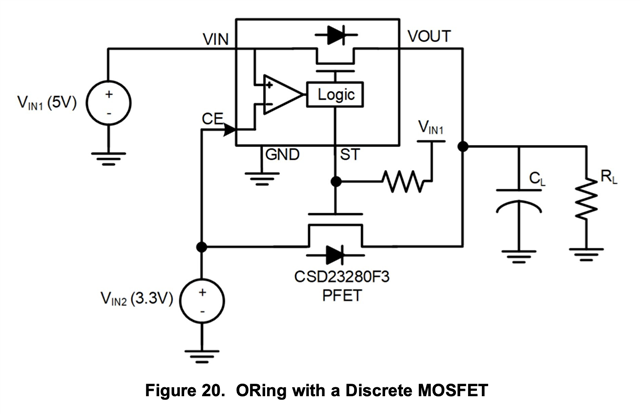
I have some questions which answers I can't find within EVM board or datasheet:

1. I want to double check that the LM66100 works well even if Vin1 is missing (0V) while Vin2 is 2.9V. If main power is disconnected, Vin1 would be floating, is a pull-down resistor at Vin be recommended of 100K-1M?

2. Do you recommend an output capacitor? Or only the 1uF Vin1 input capacitor?

3. The resistor from ST pin to Vin1, is it just acting as pull-up? Do you recommend any value to decrease leakage?

Thanks

Thanks

  • Hey Fransisco,

    1. We do not recommend this mode of operation  for DC conditions as the CE pin may be left floating for a long period of time. The idea of this setup is that there are always two sources present. If you would like to only use one channel for long periods of time, I would suggest looking at TPS2116 as an alternative device. TPS2116 is a powerMUX and can be used in that method.

    2. We typically recommend to have Input capacitance =10x output capacitance.
    3. We typically recommend 10k Ohm resistor for the ST pin. It is just acting as pull-up.

    Thanks,

    Sam

  • I didnt see that it wasnt recommended. What is the common use of  it?

    What would be the problem of using LM66100 for a long period only with VIN2? The most interesting thing about it compared it with TPS2116 is that quiescent current is very low when only VIN2 backup source is working.

  • Hey Francisco,

    It is usually used when two inputs are needed between : 1.5 V – 5.5 V.

    After relooking at the schematic, CE pin cannot be floating. For the LM 66100, we can technically leave Vin floating but please do note that exposure to absolute-maximum-rated conditions for extended periods may affect device reliability.

    Operation in the abs max range is additionally not ideal as there could be significant variation(timing, on resistance, response to inputs, etc) from datasheet specifications as these were characterized under the recommended operating conditions.

    Thanks,

    Sam