This thread has been locked.

If you have a related question, please click the "Ask a related question" button in the top right corner. The newly created question will be automatically linked to this question.

Load switch suggestion TPS61252:

Part Number: TPS61252
Other Parts Discussed in Thread: TPS61299, TPS55289, LM10011, TPS55285, TPS22996, TMUX2889, TPS22810

Dear TI

I'm Seunghyeon yun in charge of HW engineer.

We have plan for new portable device.

I would like your help in selecting parts.

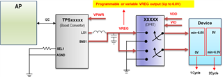
Boost converter parts(ste up boost converter, buck-Boost Converter) as shown below.

<Product condition>
-----------------------------------
Vin=0.5V~3.6V

Vout = Max. 5.5V~6.0V

Current = Max 200mA under
-----------------------------------

There is no clear explanation in the datasheet.

So it's hard to select a proper part.

The parts currently being reviewed are as follows.

Which parts should I select?

TPS61252
TPS61299
TPS6122x
etc.(Your recommend)

Thanks.

  • Dear TI

    I edit product requirement.

    ---------------------------------------------

    Vin=0.5V~3.6V

    Vout = Max. 5.5V~6.0V

    Current = doesn't care.( Min100mA)

    ---------------------------------------------

    Thanks.


  • Hi SeungHyeon,

    Is the Vout = Max. 5.5V~6.0V means you need the IC to output 6V or it just need to withstand 6V.

    I think both TPS61252 and TPS61299 can meet your requirements. TPS61299 is the better choice because it has 95nA ultra low Iq and far better light load efficiency.

    Best Regards,

    Travis

  • Dear TI

    I want a converter capable of variable voltage not fixed output voltage.

    We need a programmable voltage output boost converter

    And the component's output must support up to Max6.0V.

    (Maybe we can use a output voltage from about 3.0V to 6.0V adjustably.)

    Which parts do you recommend?

    Is it same parts you mentioned?

    Please check our concept device.

    Does these have fixed output property?(TPS61252, TRS61299)

    (If you are right, we can't use it.)

    Additionaaly, I would like to get your recommend part for DPDT too.

  • Hi SeungHyeon,

    Because of the duty cycle limitation, 0.5Vin-6Vout is hard to be achieved by a single stage boost converter. Also, our IC internal circuit needs to get powered from Vin or Vout pin before being enabled, so 0.5V start up is also hard to be achieved. In order to build a solution, we would like to confirm:

    • Do you need 0.5V for start up or you need Vin drop to 0.5V after the IC is already on.
    • Do you have any other power rail when boost is not enabled.

    Best Regards,

    Travis

  • Dear Travis Wang

    We plan to use VBAT(VPWR) as the source of a boost converter.

    (Refer to an above block diagram)

    So I expect that a Vin is min. 3.0~3.3V(Cut off voltage).

    If so, please recommend an available boost.

    (We still need to use Max. Vout up to 6.0V.

    I will wait your reply.

    Thanks.

    Regarding

    Romualdo Yun

  • Hi Romualdo,

    If you don't need 0.5V Vin operation. Then you can choose TPS61252.

    This device does not have I2C block so you'll need this application note :How to Dynamically Adjust Power Module Output Voltage (ti.com)

    Best Regards,

    Travis

  • Dear Travis Wang

    As I mentioned, we should control a Vout voltage programmably.

    But, your recommend parts are fixed Vout.

    The part(TPS61252) is only adjustable regarding as initial(start up) Vout.

    Please recommend to us the parts that suit our requirements.

    --------------------- <Requirements> -------------------------------------

    Vin=3.0V~3.6V

    Vout = From 3.0~4.0V to 6.0V (Programmable)

    --> I think that I2C control is needed for above function.

    ----------------------------------------------------------------------------------

    Thanks,

    Regards

    Romualdo.

  • Hi Romualdo,

    As the app note I mentioned. You can dynamically adjust Vout by your MCU DAC or PWM:

    ti.com/lit/an/slva861/slva861.pdf?ts=1713775359327&ref_url=https%253A%252F%252Fwww.bing.com%252F

    If you don't have a DAC or PWM, you can choose TPS55289 or TPS5585, which is more expensive.

    Best Regards,

    Travis

  • Dear Travis Wang

    Thanks for your detailed information.

    I have some questions.

    -----------------------------------------------------------------------------------------------------------------------------------

    Do you mean that if we have no DAC or PWM, we have to use LM10011 for current control?

    1) Then, which part do we use for voltage current?


    When we have no DAC or PWM, You said that we can choose TPS 55289 or TPS5585.

    But Ther is no item.(TPS5585)

    2) Maybe, I think the part number is wrong.

    Please check it.

    And, 3)At TPS61252 or TPS61299, in order to control Vout level, we use a FB pin(ADC input).

    Then What is the Vout value according to Vfb Value?
    (Vout vs Vfb mapping table)

    There is no information at an application note as you mentioned(SLVA861 Document)

    -----------------------------------------------------------------------------------------------------------------------------------

    Thanks.
    Regards
    Romualdo

  • Hi Romualdo,

    1) The App note uses LM10011 for example but the design works for all parts as long as it has external voltage divider(FB pin).

    2) Sorry that I typed it wrong. It's TPS55289 or TPS55285.

    3) I can make a EXCEL calculation for you. Please send an e-mail to travis-wang@ti.com so that I can reply you with the calculation tool attached.

    Best Regards,

    Travis

  • Dear Travis Wang

    Thanks for your answer.

    If we use the converter you recommended(TPS61252,TPS55289 or TPS55285), could you recommend any DP4T that is available?

    Please refer to the block diagram for recommendation of DP4T.

    Additionally, I can't still search for a TPS55285 datasheet .

    Thanks.

    Regards

    Romualdo Yun

  • Hi Romualdo,

    I'm forwarding this thread to the support team for load switches.

    For TPS55285, the part is not released yet. I'm looping the support team for this part in the previous e-mail so you can ask them about the detail. 

    Best Regards,

    Travis

  • Thanks Travis,

    Hi Romualdo,

    I recommend TPS22996, a dual-channel load switch. One thing to note here, though, is that this device's recommended operating voltage goes up to 5.5V and the Abs Max is 6V. If the switch will be running above 5.5V for extended periods of time, I recommend using 2xTPS22810 instead, as it has a higher operatung voltage.

    Thanks,

    Patrick

  • Dear Patrick Shalton.

    Thanks for your reply.

    I understood your products can be individually controlled. So, I have one query.

    As you see an our Block Diagram,

    We need voltage gap about 6.0V between channels.

    So, when one channel fixed 6V output, is other channel possible to set 0.0V(GND)?

    At an internal Block diagram of TPS22996, when it is a OFF state, it looks like a floating state.

    I need more explanation about it.

    Additionally, How about tmux2889 is ?

    (If the channel can be individually controlled, iI think it's not bad.)

    Thanks.

    Regards

    Romualdo Yun

  • Hi Romualdo,

    When a TPS22996 channel is disabled, a pulldown resistor is connected to the output to discharge it to 0V, so it is at a known 0V state. I would still be hesitant to use TPS22996 if the inputs will be >5.5V for an extended time. TPS22810 has this feature as well.

    The TMUX2889 part would work as well, as long as the supply voltage <= 5.5V if running for an extended period of time.

    Thanks,

    Patrick

  • Dear Patrick Shalton.

    Thanks for your reply.

    But, Your attached picture is broken.

    So, I can't see it.

    Uload a picture one more.

    Thanks

    Regrading

    Romualdo Yun

  • Hi Romualdo,

    My apologies, it was pointing out the QOD feature in the TPS22996 data sheet block diagram. Please see below.

    Thanks,

    Patrick