Hello,
We are using the IGBT transistor IKW40T120 as a low-side switch with a 8 pulse train of 5KHz (D=0.5) with VGE=15V. The power supply is 800V and we expect to use this equipment with instantaneous 30A current. Each train of 8 pulses is applied every 3 seconds. The load is resistive (5W ceramic R wirewounded). We are using driver esq.zipa UCC5390-Q1 as a driver.
After some testing we found that the Vce (sat) was about 100-120 volts. I then lowered the power supply to 600 volts (Vce sat 35 volts) and then to 400 volts (Vce sat 6-8 volts). All these tests were with the same load (970 ohms).
The screenshot of the PCB and the schematic of the driver and output stage, as well as the oscilloscope waveforms are in the attached .zip. On the PCB and the schematic you can see that there are two transistors (Q5 and Q1), one is not populated.
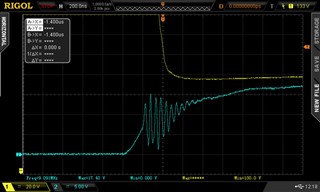
Newfile1 - Newfile 4: Vge (light blue), VCE (yellow).
Output1 - Output 5: Vload (load is 940 ohms). You can divide the value by 940 to get the current. The load is made up of 2 x 470 ohms 5 W wirewound ceramic resistors.
The measurements were made with the 800 Volt power supply.
The driver supply voltage is 15 Volts (through a 7815 that has 24 Volts input, it has 680uF electrolytic + 100nF ceramic on the output).
Seeing an oscillation while going from 0V to +15V on Vge, I suspected about the 7815 voltage regulator. The voltage in Vcc2 also fluctuated in the same way as in Vge, showing an oscillation at 10 MHz-15MHz; so I used another PSU: the same thing kept happening.
I'm measuring with x10 for the voltages at the gate and with x100 for the output and the Vce (with an important offset as you will see to be able to measure the saturation).
It's the driver stage properly settled? Could you give me some feedback?
Thanks in advance
Andrés


