This thread has been locked.

If you have a related question, please click the "Ask a related question" button in the top right corner. The newly created question will be automatically linked to this question.

UCC5390-Q1: High Vce sat on IGBT using UCC5390-Q1

Part Number: UCC5390-Q1

Hello,

We are using the IGBT transistor IKW40T120 as a low-side switch with a 8 pulse train of 5KHz (D=0.5) with VGE=15V. The power supply is 800V and we expect to use this equipment with instantaneous 30A current. Each train of 8 pulses is applied every 3 seconds. The load is resistive (5W ceramic R wirewounded). We are using driver esq.zipa UCC5390-Q1 as a driver.

After some testing we found that the Vce (sat) was about 100-120 volts. I then lowered the power supply to 600 volts (Vce sat 35 volts) and then to 400 volts (Vce sat 6-8 volts). All these tests were with the same load (970 ohms).

The screenshot of the PCB and the schematic of the driver and output stage, as well as the oscilloscope waveforms are in the attached .zip. On the PCB and the schematic you can see that there are two transistors (Q5 and Q1), one is not populated.

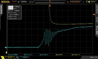
Newfile1 - Newfile 4: Vge (light blue), VCE (yellow).

Output1 - Output 5: Vload (load is 940 ohms). You can divide the value by 940 to get the current. The load is made up of 2 x 470 ohms 5 W wirewound ceramic resistors.

The measurements were made with the 800 Volt power supply.

The driver supply voltage is 15 Volts (through a 7815 that has 24 Volts input, it has 680uF electrolytic + 100nF ceramic on the output).

Seeing an oscillation while going from 0V to +15V on Vge, I suspected about the 7815 voltage regulator. The voltage in Vcc2 also fluctuated in the same way as in Vge, showing an oscillation at 10 MHz-15MHz; so I used another PSU: the same thing kept happening.

I'm measuring with x10 for the voltages at the gate and with x100 for the output and the Vce (with an important offset as you will see to be able to measure the saturation).

It's the driver stage properly settled? Could you give me some feedback?


Thanks in advance

Andrés

  • Hi Andrés,

    I do not see a high steady state Vce_sat in any of these images. The yellow CH1 lines all go down close to 0V when they are supposed to. Does 100-120V refer to a point on the tail on the falling edge?

    When closing a real switch, there is always some inductance in series, and some capacitance on the other side. This results in an LC resonance when the switch closes. This is important to consider when closing a switch with high voltage across it.

    Ringing on the Vge is usually just coupling from high voltage ringing on the Vce. But in Newfile4, I don't see ringing on the CH1 Vce that matches the ringing on Vge. This is unusual. Does the CH1 probe bandwidth exceed the ringing bandwidth of 15.62MHz?

    Maybe this is simply resonance between the driver an the gate. HR2220V801R-10 looks more like a pure inductor than a ferrite bead. Can you short it out and see if the resonance is better damped?

    Best regards,

    Sean

  • Hello Sean,

    Sorry for the confusion. This is the capture using 20V/div and some negative offset for CH1. 

    I'm using a Hantek T3100 probe (System Bandwidth DC~100MHz) with a Rigol DS2102A oscilloscope.

    The ferrite bead we are using is 7427512 

    After shorting it, the resonance went so much bigger than now (3 times)

    Best Regards

  • Hi Andres,

    It is surprising that there is no Vce ringing that maps to this Vge ringing. The transconductance of this IGBT is 21S, so they should be coupled. Maybe there is an internal resonance in the IGBT itself?

    It sounds like the ferrite bead makes a big difference. Maybe the answer is to put two in series, or use a different bead to dampen this resonance. 

    However, slowing the gate charging leads to switching losses. It is often best to improve layout and decoupling of the high power inverter to eliminate a resonant frequency. If you can find the switch node/ HV bus ringing, you can start to figure out where to add snubbers or shorten power traces.

    Best regards,

    Sean

  • Hi Sean,

    After some testing, we found that using a -5V power supply to the driver's Vee, the saturation voltage dropped to 3,2 V (altough I read that doing this only improves the negative transient from Vcc to GND, making it faster). Probably the noisy GND with some positive voltage spikes was not helping.
    Is it always recommended to use negative power supplies to the driver's Vee?
    Thanks in advance
    Best Regards