I am trying to understand the math in a simple configuration.
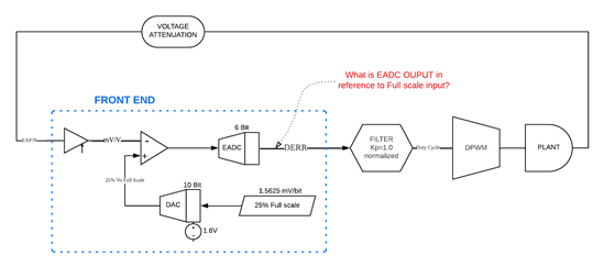
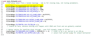
For simplicity, I am using a single filter driving DPWM 0 with the EADC DAC as the comparator value, in a voltage control loop.
The input to the EAP is scaled to 1.6V at the full scale output voltage range.
If I want to regulate the DPWM duty cycle to 25% of the Full scale output Voltage range.
Assume the filter is just 100% pass though( PID is using just P at 100%).
I have a simple question regarding the calculation of the DPWM duty cycle.
Looking at the diagrams, it seems that the duty cycle is proportional to the difference between the input voltage and the DAC voltage.
So, if the EAP voltage is equal to the DAC voltage then the EADC (error) output is zero.
This would create a duty cycle of zero not 25%....
What am I missing?
schematically....
Vin--->EAP--> COMP -
Vdac----------> COMP+
So Veadc = Vdac - Vin
if Vin = Vdac then Veadc = 0.