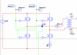
As the title suggests, using UC3846 as an H-bridge hard switch, PWM signal drives 4 MOS with a power of 20kw.
The problem is as follows:
1. Is the A and B PWM output of UC3846 complementary to pin11 and pin14? If complementary, is the maximum duty cycle not exceeding 50%?
2. If it doesn't exceed 50%, why do many people ask UC3846 about slope compensation?
3. If it is an application of H-bridge inverter, does slope compensation need to be done
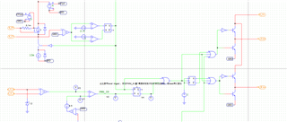
4. I made a model of UC3846, is the internal logic correct?
5. UC3846 is a chip that was released a long time ago. It is a relatively new chip that meets the requirements of H-bridge hard switching, high power, current control, and complementary PWM output. What are the recommended new models?