This thread has been locked.

If you have a related question, please click the "Ask a related question" button in the top right corner. The newly created question will be automatically linked to this question.

TPS650332-Q1: As for the fault detection items of the TPS650332-Q1 chip

Part Number: TPS650332-Q1

hi TI team

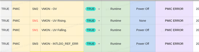
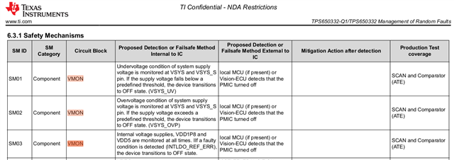
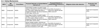
         As for the fault detection items of the TPS650332-Q1 chip, according to the fault detection items of SM1 to SM3 as shown in the following figure, the document mentions the local MCU(if there is one) or Vision-ECU detects PMIC shutdown, which conditions should be met for detection here.
         Can it be understood that external hardware is required to detect the voltage value?

1

  • Hi there,

     No external hardware is required to detect the voltage value; the chip has built-in voltage monitor for all UV, OV and OC. 

    Thanks!

    Phil

  • No external hardware is required to detect the voltage value; the chip has built-in voltage monitor for all UV, OV and OC. 

  • Thank you very much for your answer;
    For the fault detection of SM01~SM03 items above, is there a corresponding register that can be used as a basis for judgment? What are the corresponding registers?
    And what does the documentation mean by VMON?

  • Hi there,

      It seems you have not checked the device full datasheet yet. Please follow this FAQ for the device full datasheet and then find all answers from there. 

    Thanks!

    Phil

  • Thank you very much for your answer;

      According to the manual, it is still not possible to determine the corresponding registers for the fault items of SM01 to SM03. Could you please list the corresponding registers and the criteria for judgment?
      Attached is the corresponding data book.
    Thanks!

  • Hi there,

     All status registers are the corresponding registers :

    1Fh FAULT_STATUS_BUCK1 BUCK1 Fault Status Register
    20h FAULT_STATUS_BUCK2 BUCK2 Fault Status Register
    21h FAULT_STATUS_BUCK3 BUCK3 Fault Status Register
    22h FAULT_STATUS_LDO LDO Fault Status Register

    Thanks!

    Phil

  • Thank you very much for your answer:

    The following is my fault judgment logic. Can you confirm whether I understand it correctly?

    SM01

    if ((reg_1F & 0x01U) || (reg_20 & 0x01U) || (reg_21 & 0x01U))
    {
     This is the detection of the supply voltage undervoltage fault
    }

    SM02

    if ((reg_1F & 0x20U) || (reg_20 & 0x20U) || (reg_21 & 0x20U))
    {
    This is the detection of the supply voltage overvoltage fault
    }
    SM03
    if (reg_22 & 0x09U)
    {
      This is the INTLDO REF ERR fault detection
    }

    Thanks!

  • What's your "0x01U", "0x20U" meaning? Every bit there has its own meaning; please check full datasheet. 

    Thanks!

    Phil

  • Hi there,

    As shown in Figure 0X01, when bit0 is 1, it is an undervoltage fault.
    0X20 is an overvoltage fault if bit5 is 1.
    Does the above logic meet the criteria of document content。

    There are still some questions about SM03.
    Is the fault diagnosis based on the status bit of FAULT_STATUS_LDO? Can you provide corresponding logical diagnosis conditions?
    thank you

  • Hi there,

      Yes; the above logic meets the criteria of document content. 

      The fault diagnosis based on the status bit of FAULT_STATUS_LDO and we don't have other corresponding logical diagnosis conditions.

      Can you please check with your local TI FAE? so, we can have a WebEx meeting if necessary for further questions. 

    Thanks!

    Phil