Because of the holidays, TI E2E™ design support forum responses will be delayed from Dec. 25 through Jan. 2. Thank you for your patience.

This thread has been locked.

If you have a related question, please click the "Ask a related question" button in the top right corner. The newly created question will be automatically linked to this question.

LM5123-Q1: Being uncertain regard which Boost controller to use LM5123-Q1 or LM5122

Part Number: LM5123-Q1
Other Parts Discussed in Thread: LM5122

Hello, 

As a part of a power charging board I'm designing now I need a boost controller for up-converting batteries voltage while they are discharged. 

Till now I considered working with LM5123-Q1. Since it is supposed to be able to transfer 150W I was very worried regard the efficiency and therefore I have I have received from TI its excel calculator for efficiency. 

I have already chosen all the peripheral components related to it (FETs and Inductor..) and calculated the efficiency which seems ok (around 97.6%) and suddenly I encountered the LM5122 which seems to be very similar except for the package and some other things which are not so important for me in my design (for example I have enough room for the bigger size of the LM5122) but  it does have a better thermal resistance which is an important issue in my design. 

1. Is it OK to use the same excel efficiency calculator of TI called "LM5123 BOOST Controller Design Tool"  also for LM5122 ? 

2. If answer for question 1 is NO than, is there an excel calculator tool for LM5122 that you can provide me  ? 

3. Can you advice in general what boost controller has a better efficiency using same external peripheral components ? 

Thanks and BR, 

Ohad 

  • Hello Ohad,

    Thanks for reaching out to us via e2e.

    In general:
    In case of these controller ICs, the achievable power is mainly defined by the external components.
    It should be about similar for both devices.
    One difference is the dead-dime (where both FETs are OFF) which is 2x 80ns in case of the LM5122 vs. 20ns +22ns in case of the LM5123 (NOMINAL VALUES!).
    So, the time there the converter is basically inactive is longer is case of the LM5122.

    The power consumption of the controller ICs mainly depends on the voltage drop on the internal regulator.
    For Vin=8V there is basically no loss across the internal regulator. The higher the input voltage is, the more power will be consumed inside the controller IC.
    But in general, if your input voltage is maybe 12V, the power consumption is not so high that additional cooling for the controller would be required.
    Therefore, I would not consider the thermal resistance as a big issue.

    We do currently not have a QuickStart calculator for the LM5122.
    If it is only for the last section with the FET losses, the LM5123 Calculator may be close enough.
    But I am not certain how much the different dead-times will have an effect on the overall efficiency in the calculator.
    And please do not use it for anything else. You would get wrong results.

    All information in this correspondence and in any related correspondence is provided “AS IS” and “with all faults” and is subject to TI’s Important Notice (www.ti.com/.../important-notice.shtml).

    Best regards
    Harry

  • Hello Harry, 

    Thanks a lot for your answer. 

    Based on your comment, may I understand that if LM5122 has a longer Dead-time and therefore the time the converter is basically inactive is longer with LM5122 as you said: 

    the dead-dime (where both FETs are OFF) which is 2x 80ns in case of the LM5122 vs. 20ns +22ns in case of the LM5123 (NOMINAL VALUES!).
    So, the time there the converter is basically inactive is longer is case of the LM5122

    than LM5122 consume less power? I mean the switching loss and conduction loss of the FETs and inductor around the converter consume less power with LM5122 than with LM5123-Q1 because of that fact?  

    Thanks, 

    Ohad

  • Hello Ohad,

    If you were looking at it that way (assuming that everything remains the same and only the dead-time will be longer), then, as a consequence, the output power would be lower than what you actually need.
    So, it will be neccessary that during the time when the converter is active, there needs to be more energy transferred to the output (within less time).

    Due to the shorter dead-time, the efficiency of the LM5123 would be slightly better than LM5122.
    But, if you are using single FETs (ONE high side and ONE low side FET) it is more challanging to find the right EFTs an to adjust the gate resistors in case of the LM5123 because the drivers of this device are very strong and actually designed for Dual FETs (as seen on the LM5123 EVM).

    All information in this correspondence and in any related correspondence is provided “AS IS” and “with all faults” and is subject to TI’s Important Notice (www.ti.com/.../important-notice.shtml).

    Best regards
    Harry

  • Hi Harry, 

    Now I don't understand: Who has a shorter dead-time? LM5122 or LM5123-Q1? and as a result who has a better efficiency? Because in previous message you wrote LM5122 has a shorter dead-time and it is more reasonable that when dead time is shorter than power loss is smaller than efficiency is higher. And you claim the opposite. 

    Due to the shorter dead-time, the efficiency of the LM5123 would be slightly better than LM5122

    Does LM5123-Q1 can work only with dual-FETs ? 

    But, if you are using single FETs (ONE high side and ONE low side FET) it is more challanging to find the right EFTs an to adjust the gate resistors in case of the LM5123

    But if the drivers of LM5123-Q1 are so strong than why can't them support single FETs ? 

    because the drivers of this device are very strong and actually designed for Dual FETs (as seen on the LM5123 EVM).

    BR, 

    Ohad

  • Hello Ohad,

    I don't know what you are referring to.
    Anyway, what I meant to say is the following:
    The dead-dime is 2x 80ns in case of the LM5122 (NOMINAL VALUES!).
    The dead-dime is 20ns +22ns in case of the LM5123 (NOMINAL VALUES!).
    Therefore, the efficiency of the LM5123 is slightly better.

    In general, the LM5123 is a much newer device, and most parameters are better.

    The LM5123 has been designed for high power applications.
    Therefore, the gate drivers are optimized for dual FETs.
    But it can also work with single FETs.

    When you use single FETs, you will need to take care that you put gate resistors into the gate lines (between 2 Ohm and 5 Ohm as a maximum).
    And always make sure that the gate resistors for both FETs will have the same value.
    This is very important!

    If you are new to switch mode power supplies, it may be safer to use the LM5122 because itis less likely to damage the device due to a violation of the abs max ratings. 

    All information in this correspondence and in any related correspondence is provided “AS IS” and “with all faults” and is subject to TI’s Important Notice (www.ti.com/.../important-notice.shtml).

    Best regards
    Harry

  • Hi Harry, 

    Another question regard LM5123-Q1 boost. 

    According to the efficiency calculator excel quick start file, I have reached 97% efficiency when output current is 12A and Vout=9v. 

    I just wanted to make sure - does this device can support power transfer of 150W or even up to 170W when Vout=16v, Iout = 11A, Vin=9v Iin=22A or even  24A? 

    Thanks 

    Ohad

  • Hello Ohad,

    Yesterday was a public holiday for us and I am very busy right now.
    I will get back to you later today.

    All information in this correspondence and in any related correspondence is provided “AS IS” and “with all faults” and is subject to TI’s Important Notice (www.ti.com/.../important-notice.shtml).

    Best regards
    Harry

  • Hello Ohad,

    I am sorry for the delay.
    A converter which is based on the LM5123 can easily handle 200W.
    The LM5123 EVM is rated for 200W.
    It can also handle higher power levels if the power stage components are selected accordingly and get extra cooling.

    The limitation of the LM5123 is that the FETs of the power stage need to be connected directly to the controller.
    It is neither possible to use different types of switches nor external gate drivers.

    All information in this correspondence and in any related correspondence is provided “AS IS” and “with all faults” and is subject to TI’s Important Notice (www.ti.com/.../important-notice.shtml).

    Best regards
    Harry

  • Hi Harry, 

    Regard that answer you provided during our E-mailing where you emphasized that LM5123-Q1 was designed with gate drivers optimized for dual FETs : 

    The LM5123 has been designed for high power applications.
    Therefore, the gate drivers are optimized for dual FETs.
    But it can also work with single FETs

    I haven't found any reminding regard that on the datasheet and even the EVM BOM doesn't contain "Dual FET" as the higher and lower FETs on the output voltage of the boost, it recommends the single FET :NTMFS5C670NL

    So I don't understand where that claim comes from.. ?

    Thanks, 

    Ohad

  • Hello Ohad,

    I know that this is not described in words in the datasheet. All you can see there is the inner resistance of the gate drivers.
    That's why I have mentioned it here.

    The drivers of the LM5123 are very strong.
    Therefore, when you connect single FETs, especially fast switching FETs, you may encounter quite big under- / overshoots on the switch node and the gate signals.
    This also means that a very good layout with minimized parasitics around the FETs is crucial.

    You can add gate resistors to reduce these undershoots.
    Please kaap both resistors of the same value and do not go above 5 Ohms.
    If that does not help to minimize the reduce the undershoots / ringing, please select different (slower) FETs.

    All information in this correspondence and in any related correspondence is provided “AS IS” and “with all faults” and is subject to TI’s Important Notice (www.ti.com/.../important-notice.shtml).

    Best regards
    Harry

  • Hi Harry, 

    It is also not mentioned is the EVM doc and single FETs are connected there. From here come my questions: 

    1. What FETs are recommended for working with that device? I took those appear in the EVM doc: NTMFS5C670NLT1G, are they good enough to not suffer from those phenomena?  Shall I add them 5ohms on the gates? 

    2. How much slow you think the FETs shall be? What turn - ON/OFF time?  I'm afraid slower resistors may increase power dissipation because thr longer turn-on/off time -> Transistors Switching power dissipation is increased. 

    Thanks, 

    Ohad

  • Hello Ohad,

    Maybe there is some miscommunication here.
    Dual FET means two FETs in parallel on the LO driver and two FETs on the HO driver (with individual gate resistors).

    The original LM5123 EVM is using exactly this constellation: two FETs for the low side and also two FETs on the high side.
    See users guide: www.ti.com/.../snvu737
    I don't know what you are referring to.

    The NTMFS5C670NLT1G FETs are fast switching.
    When removing one each without adding gate resistors, there is heavy ringing and - dependent on Vin and Vout it max even kill the controller.

    So, again, please add gate resistors when you use single FETs, maybe start with 3 Ohms.
    Then take an oscilloscope and measure the ringing.

    There is nothing more that I can recommend right now.

    Best regards
    Harry

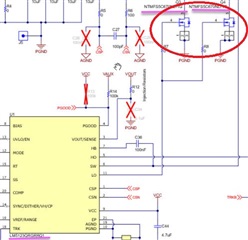
  • Ohad,
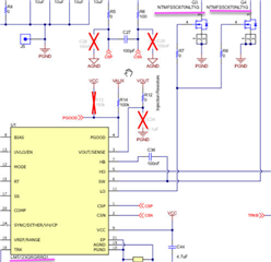
    The schematic that you had posted shows dual FETs (see red circle):

    Best regards
    Harry

  • Hi Harry, 

    Can you tell in this structure of LM5123-Q1 + NTMFS5C670NLT1G FET what will be the drive current ? 

    I asked it since I afraid that may influence on the heating dissipation of the FET because of long t-on/t-off as a result of adding resistor and the fact that Qg/Vgs=8n for NTMFS5C670NLT1G FET. 

    Ohad

  • Hello Ohad,

    This is nothing to worry about.
    The switching losses will be much smaller than the conducting losses.

    The LM5123 can drive multiple Amps peak. But that gate current is anyway not constant (also not during the transition time). So I cannot give you a number.
    For other controllers with weaker drivers, the transition time will automatically be longer (as if the gate resistor was already built-in into the driver inside the controller).

    Best regards
    Harry