This thread has been locked.

If you have a related question, please click the "Ask a related question" button in the top right corner. The newly created question will be automatically linked to this question.

LM5146-Q1: Ringing on FB pin when using CV - CC feedback network

Part Number: LM5146-Q1
Other Parts Discussed in Thread: LM5146, LM5117

Good day,

I have implemented the LM5146 as a CC CV regulator as described in this application note SNVAA85 https://www.ti.com/lit/an/snvaa85/snvaa85.pdf?ts=1713960130809

LM5146-Q1_Quickstart_28V-2A.xlsm

When the input voltage is between 28.4 up to 28.6 V the output stays at a constant 28 V output. Regardsless of the load on the output. Once the voltage goes above 28.6 V we see ringing on the FB pin and this results in the regulator to become unstable and the output voltage drops.

The CC and CV control is implemeted as follows:

CV:
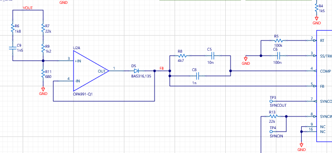
CC:

  • We also measured the Comp pin. It is mostly around 5.4V which I would think is too high. This causes the CV circuit to drop down to 0V behind the diode. 

  • Hi Martin,

    A controller for 2A at 36V max Vin is overkill. We have converters (with integrated FETs) for this application that are much easier to implement, e.g. LM61435, etc.

    I suspect the crossover may be a bit too high for Fsw = 100kHz - try a more conservative loop crossover.

    Check if the power stage is in dropout in the 28.4-28.6V input range, i.e. operating at max duty cycle, or if the loop is regulating and stable.

    Regards,

    Tim

  • Hi Tim, 

    thank you for the feedback, I first tried this with the LM5117 but realised that it cannot get close enough to the 100% duty cycle which we require. 

    We have an input voltage that swings between 20 to 32 V and is nominal at 28.8 V. I am required to charge a lithium battery at 2 A CC up to a CV of 28 V. 

    We see that upon disconnecting the CC control loop that the regulator does hold the 28 V output but it's not completely stable. With input of 28.5 - 28.9V the output is pretty much 28 V.

    With the input going 29V above we notice the output starts dropping to 27.8. 

    I will reduce the cross over frequency to match closer to 10% of the switching frequency and will the also post scope images of the different signals. Which signals in particular would be of interest to you? 

  • Hi Tim,

    I would also be open to the suggestion of the LM61435 if it will meet the 28.4 V input requirement and allow for CC and CV control.

    Best Regards,

    Martin

  • Hi Tim,

    We removed the voltage buffer and connected the voltage devider directly to the FB pin. Voltage control works perfectly now input voltages from 28.5 to 32.2 V.

    For current control we replaced the 1k resistor on the output of the difference amplifier with a diode so that the CC will not affect the voltage control. We adjusted the difference amplifier to take into account the voltage drop across the diode. We do understand that this is fairly nonlinear. 

    We were able to reduce the output resistance to 5 ohm and the regulator was able to adjust the output voltage to ensure an output current of 2 A. We do observe some unstablity as we reduce the output resistance. This I think could be due to the low 2.8A current limit set on the LM5146. 

  • Thanks, Martin. Looks like you can increase the current limit on the LM5146 and use the CC circuit to limit the current.

    --

    Tim