This thread has been locked.

If you have a related question, please click the "Ask a related question" button in the top right corner. The newly created question will be automatically linked to this question.

TPS25751: Initial setting need?

Part Number: TPS25751
Other Parts Discussed in Thread: BQ25792, TPS25750, TPS62903, MSPM0G3507

Hi Team,

I would like to check two items with you.

1. Do we need to set any initial code for TPS25751 via I2C? I asked because I see there is EEPROM on EVM. Not sure if it needs in real design.

2. Can I use DP/DM(GPIO4/5) to control TPS25751 GPIOs and TPS25751 I2C master bus?

Regards,

Roy

  • Roy,

    EVM uses EEPROM to load the firmware. We recommend having this connected to I2Cm 

    You cannot use the DP/DM to control the PD controller. Only the I2Cs bus

  • Hi Christodulos,

    Thanks for comments.

    So GPIO4/5(DP/DM) are only for BC1.2 support. We can't use DP/DM to control TPS25751, is it correct?

    Regards,

    Roy

  • That is correct. 

  • Hi Christodulos,

    If we want to configurate our GPIOs, may you help check if below procedure is ok?

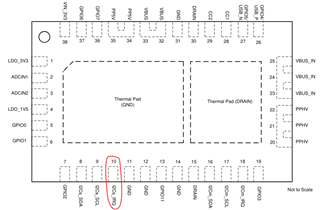
    1. Check I2C slave address from ADCIN1 and ADCIN2.

    2. Access 0x72 GPIO_STATUS Register

    - For the first 4byte, bit8 to bit0, it looks like that the configurate the GPIOs as input or output

    - For the last 4byte, bit12 and bit8 to bit0, it shows the GPIO status if the GPIO configurate as input type.

    Questions here are

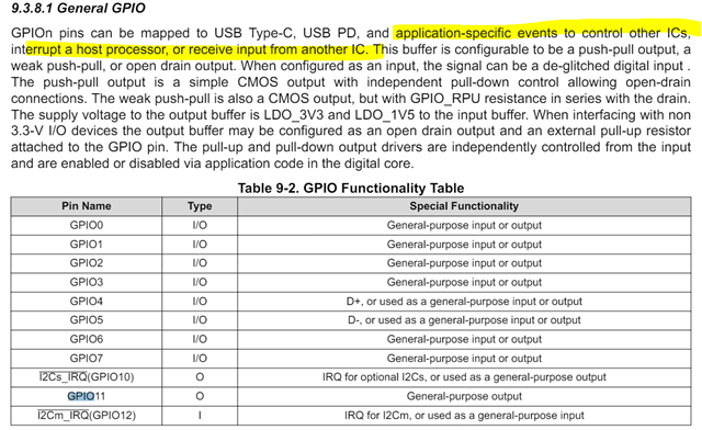
    1. If we set GPIOs as output type, how can I assign the output logic? (which register?)

    Feel free to correct me if I have any misunderstanding in above statement. Thank you.

    Regards,

    Roy


  • Roy,

    GPIOs cannot be configured from I2C writes. They are static once loaded from EEPROM. You can configure them by going to Advanced Configuration -> IO Config register. 

    The 0x72 register is a Read-Only register you cannot change direction or output valuess here. Only read the current status. 

    IO config register allows changing output logic. 

  • Hi Christodulos,

    May you comment the question that I post below?

    1. What do you mean about "Advanced Configuration -> IO Config register", can you let me know which section should I read in datasheet or user guide?

    2. Do you mean that the GPIO only can be configured by EEPROM via I2C master? 

    3. If our batter charger is BQ25792, is it essential to connect both each other?

    4. If we want to shut down the power path between TPS25750 and downstream device in some special conditions, can we use I2C to control? (TPS25750 is I2C slave and we have MCU as master)

    Regards,

    Roy

  • 1. What do you mean about "Advanced Configuration -> IO Config register", can you let me know which section should I read in datasheet or user guide?

    https://www.ti.com/lit/pdf/slvucr8

    Section 3.22

    2. Do you mean that the GPIO only can be configured by EEPROM via I2C master? 

    PD read from EEPROM so yes. But you cannot use the I2Cm to change these settings after loaded from EEPROM.

    3. If our batter charger is BQ25792, is it essential to connect both each other?

    BQ25792 and EEPROM should connected to I2Cm. PD controls both

    4. If we want to shut down the power path between TPS25750 and downstream device in some special conditions, can we use I2C to control? (TPS25750 is I2C slave and we have MCU as master)

    You can use 4CC I2Cw command to write to the BQ25792 from the I2Cs that the MCU is connected to.

  • Hi Christodulos,

    Thanks for comments. Let me summarize our hardware first. We have TPS25751(typeC controller), BQ25792(battery charger) and MSPM0(controller).

    1. In our condition, we let MCU control both of BQ25792 and TPS25751(I2Cs) which means that BQ25792 isn't controlled by TPS25751. Is it ok? 

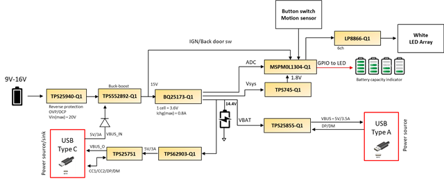
    2. In addition, if we want to shut down the VBUS from typeC connect, you suggest disable the Vbus as TPS62903 in the functional block diagram, is it correct?

    3. There is no way that can manually shut down the TPS25751 internal MOSFET, is it correct?

    4. As you said, TPS25751 GPIO can't be configured by its I2Cs. May you share the common action for I2Cs in other end users? 

    Regards,

    Roy

  • 1. In our condition, we let MCU control both of BQ25792 and TPS25751(I2Cs) which means that BQ25792 isn't controlled by TPS25751. Is it ok? 

    Yes. BQ can also support controlling it but there is no problem with this as well. 

    2. In addition, if we want to shut down the VBUS from typeC connect, you suggest disable the Vbus as TPS62903 in the functional block diagram, is it correct?

    This is one way to do it and the system seems to have ability so yes this will work! 

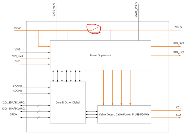
    3. There is no way that can manually shut down the TPS25751 internal MOSFET, is it correct?

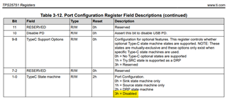
    There is but requires MCU to write to 0x28 (Port Config) register:

    To be clear, There are many ways to disable VBUS. It depends on how you want to do it. This option works or disabling TPS62903 also works. 

    4. As you said, TPS25751 GPIO can't be configured by its I2Cs. May you share the common action for I2Cs in other end users? 

    Can you elaborate? This is very much system-dependent I cannot give advice on what GPIOs to use since all systems are different. 

  • Hi Christodulos,

    Thanks for comments. For question#4, I just curious why we design the TPS25751 GPIO can only configured by I2Cm instead I2Cs. Because if we can use MCU(master) to control TPS25751 GPIO by I2Cs, the design will be flexible. 

    Unless, our scenario is the TPS25751 read EEPROM initially via I2Cm and setup all the GPIO initially. 

    And I want to know the action that other customers did with using I2Cs. May you just show me some examples? Maybe do below configuration change.

    There is but requires MCU to write to 0x28 (Port Config) register

    Regards,

    Roy

  • Because our devices do not support dynamic changing of GPIOs. All GPIOs are left in Open-Drain state until EEPROM is read and PD is in APP mode. 

    And I want to know the action that other customers did with using I2Cs. May you just show me some examples? Maybe do below configuration change.

    I cannot provide this information but I have given you some input on how it can be accomplished. 

    Thanks,

    Chris

  • Hi Chris,

    Thank you. I want to check the purpose of the I2Cs_IRQ. If I want to have an interrupt that report the typeC connector has device inserting. Can I configure the pin as interrupt pin? Thank you.


    Regards,

    Roy

  • Yes that can be done. Yes the Interrupt Mask for I2C1 register 0x16. 

    Thanks,

    Chris

  • Hi Chris,

    Thank you. Which register would you recommend for interrupt?

    Actually, we tried to set 0x16 and mask off

    PlugEarlyNotification

    SnkTransitionComplete

    PlugInsertOrRemoval

    But I2s_IRQ doesn't report low when Itried to plug in/off the typeC device (Samsung S21+)

    Regards,

    Roy

  • You would need to disable all of the interrupt masks and start there. There are numerous reasons why some would be asserted. You can also read-back the I2C Event register to find more details. 

  • Hi Chris,

    May you help check if my below flow is ok or not?

    1. Power on the TPS25750

    2. Set 0x16 = 0x0 (mask off all of the interrupt event) The I2Cs_IRQ would report low if any interrupt event occurred.

    3. Read 0x14 to know which event reported.

    Regards,

    Roy

  • Correct. Also clearing 0x16 at startup may not work because if there is an interrupt at startup, it will be asserted. 

  • Hi Chris,

    Thank you for your information.

    In addition, I believe the TPS25750 is config as DRP first. Is it possible to config as sink only?

    I see below section in user guide, but not sure how to set it.

    In addition, do we need to set any initial I2C setting to TPS25750 to let it support DRP with 5V@1.5A and 3A?

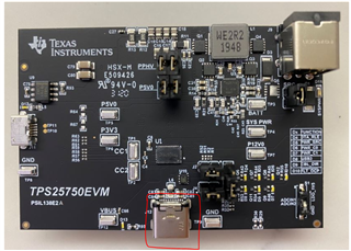
    I asked because we used EVM and ensure the Vbus has 5V and we try to connect our cellphone to EVM's typeC connector, but no charge current through the typeC cable.


    Regards,

    Roy

    Regards,

    Roy

  • Is it possible to config as sink only?

    Yes this is in the 'Select you Configuration' step.

    any initial I2C setting to TPS25750 to let it support DRP with 5V@1.5A and 3A?

    This is configured in your Transmit Source/Sink Capabilities and by question 2 and 3. 

    I see below section in user guide, but not sure how to set it.

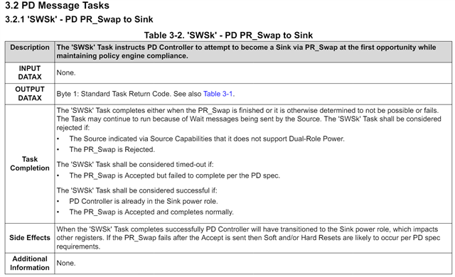
    Read about the CMD/DATA registers and how 4CC commands are sent. Just write the 4 ASCII characters 'SWSk' to the CMD register. No Data is needed here. 

  • Hi Chris,

    1. I want to double check if this "0 Port Configuration Register (Offset = 28h)" register can switch the typeC mode?

    2. I want to double check if this "Port Control Register (Offset = 29h) [Reset = 03915052h]" can control the type C current?

    Regards,

    Roy

  • Both are correct. 

  • Hi Chris,

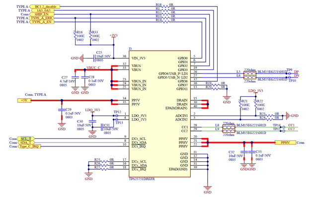
    Thanks for confirmation. Today we receive our typeC system board. Please see below picture. We don't use EEPROM to configure it. For the GPIO, in the future, we won't use it because as discussion before, it should be configured by I2Cc via EEPROM.

    Now, I connect I2Ct to our MCU(MSPM0G3507) to let our MCU config the typeC controller.

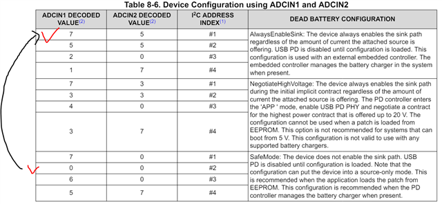
    In the beginning, we can't read the I2C address that we set in ADCINx. (0/0 #2) I tried to change to 7/5#1 and I can read TPS25751 address(0x20)

    Question #1:

    1. Not sure why the table comment's title is dead battery configuration. May you help comment it?

    Question#2:

    2. In our application, we only used 5V/3A or 1.5A with source or sink. Does current device configuration is ok? (7/5#1)

    Question#3:

    If we don't use EEPROM to load the patch, does it make sense that we can't read the TPS25751 I2C address?

    Question#4:

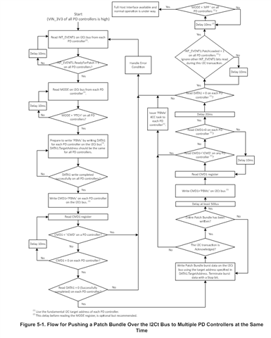
    Now we read 3h and the mode showed that we were in PTCH mode. As I know, I need to follow below instructions to enter in APP mode. Is it correct?

    Question#5:

    Do you have sample code for it? (PTCH to APP)

    Question#6:

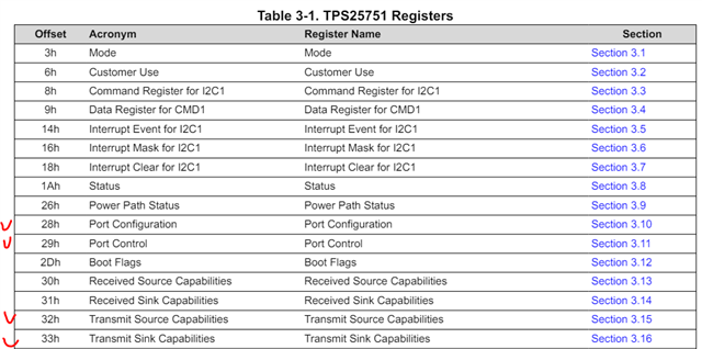
    After entering in APP mode, we only need to set our desired 28h/29h/32h/33h and typeC controller can be operated. Is it correct?


    Regards,

    Roy

  • Roy, 

    This thread has been open for 4 weeks and the original question has been answered. I will be answering this question then closing this E2E. If you wish to ask more queries you may in new threads. It is expected one thread, one topic. 

    1. Not sure why the table comment's title is dead battery configuration. May you help comment it?

    Please look at Datasheet and USB-PD spec for more on DeadBattery. It is when PD controller/system is powered from VBUS. 

    2. In our application, we only used 5V/3A or 1.5A with source or sink. Does current device configuration is ok? (7/5#1)

    ADCIN configuration here is irrelevant. This is setup in configuration. 

    If we don't use EEPROM to load the patch, does it make sense that we can't read the TPS25751 I2C address?

    Yes. Your configuration is not loaded. PD is in PTCH mode. 

    Is it correct?

    Yes

    Do you have sample code for it? (PTCH to APP)

    We provide the flow you see there. I recommend just loading from EEPROM. 

    After entering in APP mode, we only need to set our desired 28h/29h/32h/33h and typeC controller can be operated. Is it correct?

    I do not know whole system requirements so cannot say. But those are important for setup of system. 

    Thanks,

    Chris