This thread has been locked.

If you have a related question, please click the "Ask a related question" button in the top right corner. The newly created question will be automatically linked to this question.

TPS56A37: Problem with customer DC/DC module. Short circuit after first successful tests.

Part Number: TPS56A37

Hello Community/TI Team!


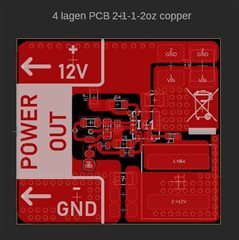
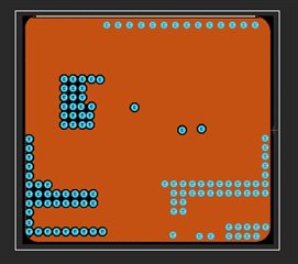
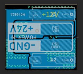
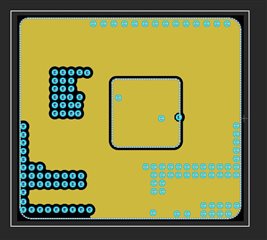
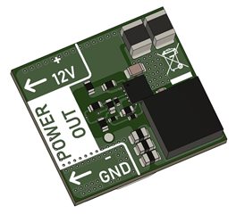
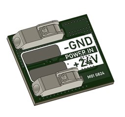
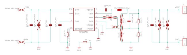
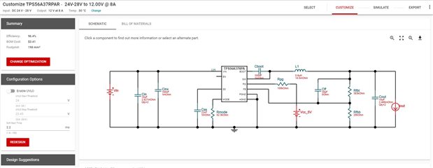
We have produced a small 24V to 12V PCB DC/DC module with the new TPS56A37 (4.5V to 28V Input, 10A, Synchronous Buck Converter). At the moment it should be loaded with max. 4A. The circuit is based on the Webench Power Designer Design. The PCB (4 Layer) layout is based on the design of the TPS56A37EVM evaluation module.

The first tests with five prototype modules were very promising. We tested the temperatures with different loads. All good so far.

After a few days we wanted to continue the tests. However, all the modules broke. 

Setup:

Customer TPS56A37 voltage regulator PCB module prototype (22x20mm)

24V input, Rhode & Schwarz & , Peak Tech laboratory power supply (current limitation to approx. 100mA)

No output load connected


When the power supply was then switched on, there was an immediate short circuit, which could then be measured with a measuring device. No 12V output and the TPS45A37 get hot.

We are currently unable to explain what caused this problem, as we noted good results a few days before. We tested the two different laboratory power supplies and checked the polarity and settings of the power supply using the four-eyes principle. Everything was set up correctly.

Do you have any tips on what caused the destruction of the TPS56A37 or how we can localize it?


We would be very pleased to hear from you.

1565.Schematic.pdf

  • Hi Benjamin

    There is no electrolytic capacitor on the input side. Can you capture the Vin waveform when power up? Is there any long cable from the power source to the input of the  TPS56A37 ? If there is long cable and the Vin rise is fast, there can be ringing/overshoot on the Vin of TPS56A37. 

    One other thing is that I can't see the part number of C7, the ceramic cap will have derating under DC bias,  can you please check effective capacitor value under 12V DC bias? I think the Cout effective value is too small.

    By 'All the modules broken' , did they powered up together and got damaged together all that you reproduced the damage?

    Thanks and best regards.

  • Hello!

    • I will test it with a electrolytic capacitor on the input side.
    • The cable on the input source is arround 2m. Later in the planned product application, the input lengths may become even longer. It will be used in home automation with the power supply unit installed away from the application.
    • Currently I have no measurement from the Vin waveform, but it´s a good advice
    • I will change the C7 value

    We did not connect the modules together/simultaneously. One at a time to find out where the problem was. Maybe we had shorter cables at the power supply during the first postitive tests a few days before. I can't check that at the moment. That could possibly explain the different states.  

    We will ordner new parts and make new tests.


    Thank you for your help!

  • Hi Benjamin

    Thank you for your update. 

    BR.