This thread has been locked.

If you have a related question, please click the "Ask a related question" button in the top right corner. The newly created question will be automatically linked to this question.

LM3481: How to control Output Level

Part Number: LM3481

We want to the following Specifications:

Vin = 12V

Vout = 24V, 2A

V Output Control with PIO pins.

The circuit diagram we currently use is as follows.

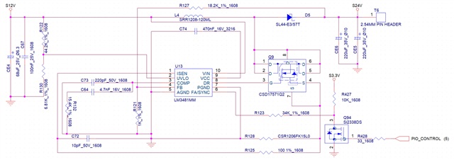
PIO Control L(0V) = Vout 12V

PIO Control H(3.3V) = Vout 24V

 We want the output level to be 0V.

Please let me know how th modify the circuit.

  • Hi Jaewook,

    Thanks for using the e2e forum.

    Please help me clarify their design goal.
    Right now the output of their Boost design will be regulated to 24V.
    Now they want an adjustable output voltage, to switch between 12V and 24V output voltage. Is this correct?
    As the input voltage is already 12V, to achieve 12V the device would just go into standby mode.

    Their PIO_CONTROL signal is connected to the FA/SYNC pin of the device. This pin is for setting the switching frequency or synching to an external clock signal.
    To adjust the output voltage, they would need the change the feedback resistor at the FB pin.
    To disable the device, they would need to pull low the UVLO pin.

    Best regards,
    Niklas