This thread has been locked.

If you have a related question, please click the "Ask a related question" button in the top right corner. The newly created question will be automatically linked to this question.

TPS25750: leakage current issue

Part Number: TPS25750
Other Parts Discussed in Thread: BQ25792, , BQ40Z50, TPS25751, BQ40Z50-R2

To whom it may concern:

We are using the TPS25750 for a USB-PD and BC1.2 protocols design. Previously we received the BIN from TI, and everything seems working properly. However, after further test, this BIN file causes a very high leakage current on the TPS25750 IC, about 2.5-3mA. If we use the old BIN file, which didn't have BC1.2 coverage, the leakage current of the entire board, including TPS25750, BQ25792, BQ40Z50 and an MCU, is only 360uA.

Could you help to take a look at the BIN file and make the necessary updates?

I will share the BIN file separately since I have trouble to upload the file here.

Thank you!

Chen

  • Hi Chen,

    Please give the team a couple days to look into the issue and provide feedback.

    Where are you measuring the leakage current? Vin3V3? D+/D-?

    Can you share your schematic?

    Do you have json files as well? You should be able to just drag them into the E2E thread from file explorer.

    Thanks and Regards,

    Chris

  • Hello Christopher:

    Thanks for your reply. Yes I can share the schematics, but I have trouble to upload it here. I will ask our FAE to pass it to you.

    The leakage is on VIN_3V3.

    I don't have the JSON file, since the BIN file was generated directly by TI (Field).

    Our expectation of the charging behavior:

    USB-C/PD input:

    5V/3A

    9V/2A

    12V/2A

    15V/2A

    20V/2A

    Legacy protocols:

    5V/0.5A

    So other than USB-C/PD, all other 5V input can be limited to 0.5A.

    Thanks!

    Chen

  • Hi Chen, 

    Is this a sink only design?

    Field is not currently supporting these products but I am trying to reach out to see if he still has some of the design files.

    Can you also specify the names of the two bin files you mentioned? Bilge shared the bin files but there are 4 of them so I want to make sure I test the correct ones.

    It looks like C3DCP_ChenReq_18Dec is the BC1.2 one?

    Also, I'm assuming you are testing with nothing connected when measuring the current?

    Thanks and Regards,

    Chris

  • Hello Chris:

    Thanks for your reply. And yes it is sink only.

    We confirmed that all 4 of the BIN files in that email had the high leakage current issue. The "old" BIN file with normal leakage was generated directly from the online configuration tool, but it can't support any legacy protocol.

    The testing was done with all ICs connected. But when using the old BIN file, the leakage is only 350uA; with the 4 in the email, including C3DCP_ChenReq_18Dec, the leakage current is about 3mA. Same board were used.

    BTW, the charger IC is BQ25792. And pre-charge current is 400mA ideal, and 100mA minimum.

    Thanks!

    Chen

  • Thanks for the information Chen,

    Please allow a couple days to test and respond.

    Thanks and Regards,

    Chris

  • Hello Chris:

    How is going? Any update on this? We are under great pressure and the entire system is waiting for the solution. Much appreciate for the help.

    Thank you!

    Chen

  • Hi Chen,

    Can you check the I2Cm lines coming from the PD controller and report the voltage? During testing with an EVM, I'm seeing similar current draw issues when loading the binary, and it looks like one of the I2C lines is being pulled low. If this is tied to LDO3V3, it could cause additional power draw.

    Thanks and Regards,

    Chris

  • Hello Chris:

    We tried the votlage on I2Cm, and both of them are pulled up by LDO3V3. Then we tried further with old BIN file, and they are also get pulled up. 

    We also tried to remove the EEPROM IC, but the leakage current is the same.

    Could you help to generate a new BIN file? I think we have all the configuration expectations in the email from FAE.

    Thanks.

    Chen

  • Hi Chen,

    I'm still doing some testing on my end. Field provided me a json file to generate the bins, but whenever I do, the I2C lines are getting pulled low. I had originally thought that was the cause of the additional loading, but that does not seem to be the case from your feedback.

    Thanks and Regards,

    Chris

  • Hello Chris:

    So based on your test, the I2Cm lines are pulled low, which cause the leakage from LDO3V3 to GND. Let me double check and confirm agian.

    Thanks.

    Chen

  • Hi Chen,

    This is just what I noticed on initial boot up. In parallel I'm checking with the team to see if enabling BC1.2 may cause additional current draw. It will enable a feature that senses the D+/D- lines, and I'm not sure if there is additional circuitry that draws power during this time,

    Thanks and Regards,

    Chris

  • We also tried to remove the EEPROM IC, but the leakage current is the same.

    I also tried disconnecting the EEPROM, also seeing higher leakage current.

  • Hi Chen,

    The I2C issue is related to the EVM, it does not support the BQ controller you are using.

    I found another setting that affects the current draw.

    Please try these binaries, I think they should resolve the leakage current issue.

    https://e2e.ti.com/cfs-file/__key/communityserver-discussions-components-files/196/CACDP_5F00_CHENReq_5F00_8MAY.bin

    https://e2e.ti.com/cfs-file/__key/communityserver-discussions-components-files/196/CADCP_5F00_CHENReq_5F00_8MAY.bin

    Thanks and Regards,

    Chris

  • Hello Chris:

    Thank you very much. We will test and let you know.

    Chen

  • Thanks, please check the VIN3V3 current.

    Thanks and Regards,

    Chris

  • Hello Chris:

    We did some initial test, and seems like the leakage current got decreased to 500uA average. It is still higher than the old BIN at 350uA, but much better.

    However, when we test the USB 2.0 charging, which is 5V 0.5V (2.5W) from computer, the power draw is higher than expected. The BQ40Z50 read the charging current as 400mA, and the voltage is about 8V, so the power was over 3.2W. This could be a potential risk if any legacy protocols were connected.

    Voltage Current
    8025 402
    8031 401
    8035 402
    8042 402
    8047 401

    Please help to check.

    Thanks!

    Chen

  • Hi Chen,

    What do you mean by the votlage is 8-V? Is this VBUS? VSYS?

    When you say USB2.0 charging, is the PD controller acting as sink or source?

    Do you want to reduce the charging current? From the emails, it sounds like you and Field agreed to set it a 400mA?

    If I understand correclty, you are only expecting to draw 2.5-W, but 3.2 is being drawn? Can you measure the output power at the USB-C port to see how much power is being drawn?

    Thanks and Regards,

    Chris

  • Hello Chris:

    Thank you very much for your prompt reply.

    1. The battery voltage is about 8V, so VBAT and VSYS were 8V.

    2. This is a sink only application. The PD controller is connected to the computer USB2.0 port, and the voltage and current were read from BQ40Z50 fuel gauge IC. So the battery was charged at 400mA, and the voltage is 8V, which means 3.2W on the battery.

    3. We would like to have 400mA for precharge; however, the charging power should not overdraw the power from the USB port.

    4. Yes, the USB2.0 port only supports 2.5W, but the PD controller and charger drew more than 3.2W (considering efficiency). For USB-C/PD adapters, they have the current/power as expected based on our test so far.

    -------------------------------------------------------------------------------------------------

    Back to the configuration expectation:

    1. For USB-C/PD, the input current of the PD controller(current draw from adapter or USB port):

    5V/3A, 9V/2A, 12V/2A, 15V/2A, 20V/2A

    2. For any legacy USB: 5V/0.5A

    3. Precharge current: 400mA ideal (limited by the input), 100mA minimum. 

    4. Normal charge current: 2A ideal (limited by the input)

    Please help to check the BIN file. Let me know if you need more information.

    Thanks again!

    Chen

  • Hi Chen,

    Would it be possible to obtain a I2C log of the traffic between the PD controller and BQ25792 when the usb-c cable is connected?

    Specifically, I want to see if there are any writes to reg0x06,Input Current Limit.

    Because we hard set the precharge to 400mA, the BQ needs to limit the power draw from the input side. We need to check to see what value the PD controller is updating with.

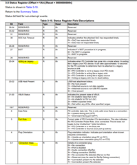
    Also, could you check and report the status of these bits when the system is hooked up and drawing power?

    Thanks and Regards,

    Chris

  • Hello Chris:

    We are still collecting the data as you required. At the meantime, do you have any BIN update?

    Our expectation is pretty simple. It is a sink only device.

    USB-C/PD (input): high input current: 5V/3A, 9V/2A, 12V/2A, 15V/2A, 20V/2A

    USB legacy protocols (input): 5V/0.5A

    Precharge current (output): 100mA minimum, 400mA ideal (but not over the power supply limit)

    Fast charge current (output): 2A (but not over the power supply limit)

    Thank you!

    Chen 

  • Hi Chen,

    Some of the changes you are asking for rely on the results of the data.

    The PD controller set's the Precharge current to a fixed value, in this case 400mA. It does not set a "minimum".

    The TPS25750 does not update the Input Current limit for different sink PDOs. In the case of the legacy charging, the PD controller does not update the BQ to draw less power. An EC/MCU would be needed to do this. The successor part, TPS25751 has some fixes that 

    Here is a binary with some changes made:

    https://e2e.ti.com/cfs-file/__key/communityserver-discussions-components-files/196/CA_5F00_ChenReq_5F00_21May.bin

    Thanks and Regards,

    Chris

  • Hello Chris:

    Thank you very much for the update. So for TPS25751, it can fix this problem?

    Also, if we keep using TPS25750, we may need MCU to control the current? Will the TPS25750 identify the USB legacy protocol and MCU can check?

    Thank you!

    Chen 

  • Hi Chen,

    One thing that was added for PD contracts is a feature that takes the active source/sink contract and programs specific BQ parts to limit power sourcing/draw according to the active contract. This is something not in TPS25750.

    BC1.2 is a weird case. After checking with the team, it should help fix the problem, but the voltage/current programming may not cover all cases for legacy charging. The feature currently works for PD, and is partially working for BC1.2. The team is currently working on implementing some of these features.

    Also, if we keep using TPS25750, we may need MCU to control the current? Will the TPS25750 identify the USB legacy protocol and MCU can check?

    Correct, the TPS25750 does not update the BQ and you may need to check the connection status with an MCU and update the BQ appropriately.

    Thanks and Regards,

    Chris

  • Hello Chris:

    Thanks for the confirmation. We are trying to get some TPS25751D for testing.

    Could you help to confirm, if the TPS25750 can identify the USB legacy protocols? And is it possible to disable all the legacy protocols? So the battery will only be charged on USB-C or PD, and won't response to the USB2.0 or any others. In this case it won't overdraw current from legacy USB port.

    Thanks!

    Chen

  • Hi Chen,

    Due to the holiday in the US, many of the device experts are currently out of the office. When they return they will look into this and provide a response. Please expect some delay accordingly.

    Thanks,
    Field

  • Hi Chen,

    The TPS25750 can identify BC1.2, are there other legacy protocols you are thinking of? It will identify, but as mentioned before, it will not update the Battery charger appropriately for BC1.2 contracts.

    Yes, it is possible to disable BC1.2 and some other legacy protocols.

    Attached is a binary with BC1.2 and legacy protocols disabled.

    https://e2e.ti.com/cfs-file/__key/communityserver-discussions-components-files/196/CA_5F00_ChenReq_5F00_28May.bin

    Thanks and Regards,

    Chris

  • Hello Chris:

    Great. Thank you very much for the confirmation. We will try this BIN file, and also test the TPS25751D IC. If we are using TPS25751D, I would assume a new BIN file will be needed.

    Thanks!

    Chen

  • Hi Chen,

    If we are using TPS25751D, I would assume a new BIN file will be needed.

    Yes, that is correct. With the new part, we released an updated GUI that has very similar questions, but will require generating a new project. I would recommend looking at the GUI first.

    Thanks and Regards,

    Chris

  • Hi Chen,

    Here is the link and password for the external TI Drive. Do not put anything NDA restricted in here, it contains the .exe for the Web GUI that we talked about.

    https://tidrive.ext.ti.com/u/9vVARyT1QFHk9UBV/6cf99962-16d8-4c4e-83cd-7c3f734004eb?l

    |2YkF27M

    Thanks and Regards,

    Chris

  • Hello Chris:

    Could you also share the link for online use?

    Thank you!

    Chen

  • Hi Chen,

    https://www.ti.com/product/TPS25751

    Please try the config tool link found on the product page.

    Thanks and Regards,

    Chris

  • Hello Chris:

    We are trying the part TPS25751, and I have two questions while generating the BIN file:

    1. For BC1.2, it only stated CDP, DCP. Can we just use SDP?

    2. For the "Dead Battery clear threshold", it is fixed and can't change. Can we just set a value for the TPS IC clear the DBfg automatically?

    Thank you!

    Chen

  • Hi Chen,

    1. For BC1.2, it only stated CDP, DCP. Can we just use SDP?

    Unfortunately, the register fields for BC1.2 in the port config register only allow for those two.

    2. For the "Dead Battery clear threshold", it is fixed and can't change. Can we just set a value for the TPS IC clear the DBfg automatically

    Where are you seeing this field? I'm not familiar with this setting and will need to check with the team.

    Thanks and Regards,

    Chris

  • Hello Chris:

    Thanks for your reply.

    1. If only CDP/DCP supported, how to control the current to 500mA for USB2.0 and other legacy protocols? Basically our expectation is all the legacy port just using 500mA, and only USB-C/PD will use higher current to charge.

    2. This is the last field of the GUI. 18) What is the dead battery clear threshold?

    Thanks!

    Chen

  • Hi Chen,

    1. If only CDP/DCP supported, how to control the current to 500mA for USB2.0 and other legacy protocols? Basically our expectation is all the legacy port just using 500mA, and only USB-C/PD will use higher current to charge.

    We are able to detect SDP, and it should fall under the "Detect BC1.2 chargers option". BC1.2 detection should handle SDP

    If you want to advertise an implicit 500mA, you should be fine just using the TypeC Current field in the port control register.

    2. This is the last field of the GUI. 18) What is the dead battery clear threshold?

    When I select the BQ2579x device in the questionnaire, this field is grayed out. Speaking with the team, it sound like this is a feature that is still being implemented and is not ready/official yet.

    Thanks and Regards,

    Chris

  • Hello Chris:

    Thanks for the information.

    1. For 500mA, if we use TypeC Current field for this, will we still have normal 5V 3A when it is USB-Type C? Our target is still the same, legacy protocols 5V/500mA, and USB-Type C/PD 5V, 3A, and other high voltage high current input.

    2. OK so for now the DBfg still need to be cleared by MCU? Do you have a timeline to have this feature published officially?

    I already generated one BIN file and it is under testing. I may seek more help if it still has issues.

    Thank you!

    Chen

  • Hi Chen,

    1. For 500mA, if we use TypeC Current field for this, will we still have normal 5V 3A when it is USB-Type C? Our target is still the same, legacy protocols 5V/500mA, and USB-Type C/PD 5V, 3A, and other high voltage high current input.

    There are a couple different negotiations here. There is legacy BC1.2, there is Type-C only, and there is Type-C PD.

    The TypeC current will limit the Type-C only to the default current, which is 500/900mA dependent on the USB speed(USB2 vs 3). The main thing here is that as source, we will advertise both of these current capabilities and be compatible with far end sink devices.

    2. OK so for now the DBfg still need to be cleared by MCU? Do you have a timeline to have this feature published officially?

    Yes, I am not sure on the timeline for this feature, It is not currently high on the priority list for development.

    Thanks and Regards,

    Chris

  • Hello Chris:

    I generated the BIN for TPS25751, but seems like it doesn't work well. The two main issues still exist:

    1. BC1.2 coverage. It still have more power pulled from USB2.0 and similar legacy port.

    2. Leakage current: the leakage current are measured as 2.5mA, a little bit better than the old one, but still too high. 

    I will share the BIN and JSON file with our FAE and pass to you, since I have trouble to upload files here.

    Could you help to generate and share the BIN file for TPS25751? The expectation is the same as before. 

    Thank you!

    Chen

  • Hi Chen,

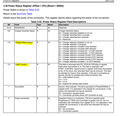
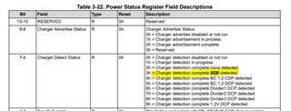
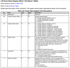
    1. Are you still acting as sink in this case? Can you confirm from register reads of the Power Status register and make sure a BC1.2 contract is entered? What do you mean by "It still have more power pulled from USB2.0 and similar legacy port"? Is a power limit hit during testing?

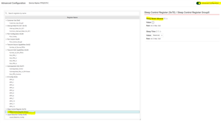
    2. In the GUI, enable Advanced Config and navigate to the "Sleep Control Register". Select the Sleep Mode Enabled field to enable the lower power mode for the PD controller.

    You can share the json and binary here by just dragging the files into the reply, I attached the files you shared below.

    {
      "questionnaire": {
        "device": "TPS25751",
        "answers": [
          null,
          4,
          4,
          3,
          1,
          0,
          3,
          1,
          1,
          1,
          1,
          0,
          0,
          0,
          12.6,
          2,
          0.12,
          0.12,
          0
        ],
        "vendorId": "0000",
        "productId": "0000",
        "version": "1.0.0.2"
      }
    }

    https://e2e.ti.com/cfs-file/__key/communityserver-discussions-components-files/196/TPS25751-prelim.bin

    Thanks and Regards,

    Chris

  • Hello Chris:

    Thank you for your reply. I made some changes to the BIN file and tested.

    1. Yes, it is SINK only. After the BIN update, we can see all 6 PDOs, including 5V/0.5A, 5V/3A, 9V/2A, 12V/2A, 15V/2A and 20V/2A. However, 5V/0.5A is not really working, and it still overdraw current from USB2.0 port. When plug into old laptop, it would alert the error on the USB port, and measured as 1A, which is double the standard 500mA.

    2. Leakage current issue is mitigated after "sleep mode" is selected. During the test, we noticed the active time is relative long, but overall it is much better than before.

    3. In the configuration, the precharge current is set to 120mA. However, it is always 400mA during precharge. Could you help to check?

    I am not sure if it is out firewall issue, or my computer, but I still can't upload files here. When I drag the files, it would show "upload" and then nothing really added. I will share the files to you directly. Sorry about that.

    Thank you!

    Chen

  • Hi Chen,

    1. Yes, it is SINK only. After the BIN update, we can see all 6 PDOs, including 5V/0.5A, 5V/3A, 9V/2A, 12V/2A, 15V/2A and 20V/2A. However, 5V/0.5A is not really working, and it still overdraw current from USB2.0 port. When plug into old laptop, it would alert the error on the USB port, and measured as 1A, which is double the standard 500mA.

    By USB2.0, do you mean USB-A or a non USB-C PD port? Those ports have different requirements than USB-C PD, and the minimum current that needs to be offered for type-C only is 900mA (~1-A), which might be why it is drawing that much current.

    3. In the configuration, the precharge current is set to 120mA. However, it is always 400mA during precharge. Could you help to check?

    How are you determining the precharge current is 400mA? Directly measuring or reading the register? If you haven't already, can you read register 0x08 (prechg current_ during this time? I checked the I2C writes, and it looks like the configuration should only be writing a value of  0x03 to register 0x08, which should correspond to 120mA. The .json you shared looked fine.

    I am not sure if it is out firewall issue, or my computer, but I still can't upload files here. When I drag the files, it would show "upload" and then nothing really added. I will share the files to you directly. Sorry about that.

    Oh, understood. No worries!

    (files you shared for tracking purposes)

    {
      "questionnaire": {
        "device": "TPS25751",
        "answers": [
          null,
          4,
          4,
          3,
          1,
          0,
          3,
          1,
          1,
          1,
          1,
          0,
          0,
          0,
          12.6,
          2,
          0.12,
          0.12,
          0
        ],
        "vendorId": "0000",
        "productId": "0000",
        "version": "1.0.0.2"
      },
      "configuration": {
        "data": {
          "selected_ace": [
            {
              "register": 6,
              "data": [
                0,
                0,
                0,
                0,
                0,
                0,
                0,
                0
              ]
            },
            {
              "register": 22,
              "data": [
                0,
                0,
                0,
                0,
                0,
                0,
                0,
                0,
                0,
                0,
                3
              ]
            },
            {
              "register": 40,
              "data": [
                0,
                0,
                47,
                0,
                0,
                0,
                0,
                0,
                0,
                0,
                0,
                0,
                0,
                0,
                0,
                0
              ]
            },
            {
              "register": 41,
              "data": [
                50,
                80,
                153,
                68
              ]
            },
            {
              "register": 50,
              "data": [
                0,
                168,
                42,
                44,
                145,
                1,
                32,
                44,
                209,
                2,
                0,
                44,
                177,
                4,
                0,
                244,
                65,
                6,
                0,
                244,
                65,
                6,
                0,
                0,
                0,
                0,
                0,
                0,
                0,
                0,
                0,
                0,
                0,
                0,
                0,
                0,
                0,
                0,
                0,
                0,
                0,
                0,
                0,
                0,
                0,
                0,
                0,
                0,
                0,
                0,
                0,
                0,
                0,
                0,
                0,
                0,
                0,
                0,
                0,
                0,
                0,
                0,
                0
              ]
            },
            {
              "register": 51,
              "data": [
                6,
                50,
                144,
                129,
                16,
                44,
                145,
                1,
                0,
                200,
                208,
                2,
                0,
                200,
                192,
                3,
                0,
                200,
                176,
                4,
                0,
                200,
                64,
                6,
                0,
                0,
                0,
                0,
                0,
                0,
                0,
                0,
                0,
                0,
                0,
                0,
                0,
                0,
                0,
                0,
                0,
                0,
                0,
                0,
                0,
                0,
                0,
                0,
                0,
                0,
                0,
                0,
                0
              ]
            },
            {
              "register": 55,
              "data": [
                59,
                192,
                18,
                65,
                144,
                145,
                1,
                0,
                0,
                0,
                0,
                0,
                0,
                0,
                0,
                0,
                0,
                0,
                0,
                0,
                0,
                0,
                0,
                0
              ]
            },
            {
              "register": 92,
              "data": [
                12,
                12,
                0,
                0,
                0,
                0,
                0,
                0,
                0,
                0,
                0,
                0,
                0,
                4,
                0,
                0,
                0,
                4,
                0,
                0,
                0,
                0,
                0,
                0,
                0,
                4,
                0,
                0,
                0,
                0,
                0,
                0,
                0,
                0,
                0,
                0,
                0,
                0,
                0,
                0,
                0,
                0,
                0,
                0,
                0,
                0,
                0,
                0,
                0
              ]
            },
            {
              "register": 112,
              "data": [
                3
              ]
            },
            {
              "register": 152,
              "data": [
                0,
                0,
                0,
                0,
                0,
                0,
                0,
                0,
                0,
                0,
                0
              ]
            }
          ]
        }
      }
    }

    https://e2e.ti.com/cfs-file/__key/communityserver-discussions-components-files/196/TPS25751-BIN-Prelim-07_2D00_09_2D00_2024.bin

    Thanks and Regards,

    Chris

  • Hello Chris:

    Thanks for your reply. For the questions above:

    1. USB2.0 port refers to the port on the old computers used for keyboard or mouse connection, and they should have 500mA limit. We just want to cover all legacy protocols with 5V 500mA. Could you help to configure the BIN file to cover this?

    3. 400mA is ready from the battery fuel gauge, which is BQ40Z50-R2 IC. I believe the configuration is 120mA, as you verified.

    So at this point, I think we still have some missing point as we had before. Could you help to generate the BIN file, which can cover:

    1. Sink only. Charging voltage: 12.6V, charging current: 2A (or limited by the input), taper current: 120mA, pre-charge current: 120mA

    2. USB-C/PD: input: 5V/3A, 9V/2A, 12V/2A, 15V/2A, 20V/2A

    3. Any legacy USB port: 5V/0.5A

    Thank you very much!

    Sincerely,

    Chen Jia

  • Hi Chen,

    Give me a couple days to review this info and provide feedback.

    I'm a little hesitant about item 1. My understanding is that for A to C cables, they will set the RP pullup resistors on the CC lines to the lowest current settings. In the spec, the lowest "standard" current can be either 500mA or 900mA, it is somewhat ambiguous, so I'm not sure what will happen there.

    Thanks and Regards,

    Chris

  • Hello Chris:

    Thank you very much!

    For 1, do you think if we can change our schematics/hardware to make it work? I don't think this is a very odd requirement for backwards compatibility. 

    Thanks.

    Chen

  • Hi Chen,

    1 is a limitation of the way our PD controller handles the spec, I'm checking to see what else can be done. You could maybe use an I2C host to see the active contract and update the BQ manually.

    Thanks and Regards,

    Chris

  • Hi Chen,

    See the attached json and binary with the settings you requested on the 24th.

    {
      "questionnaire": {
        "device": "TPS25751",
        "answers": [
          null,
          4,
          4,
          3,
          1,
          0,
          3,
          1,
          1,
          1,
          1,
          0,
          0,
          0,
          12.6,
          2,
          0.12,
          0.12,
          0
        ],
        "vendorId": "0000",
        "productId": "0000",
        "version": "1.0.0.2"
      },
      "configuration": {
        "data": {
          "selected_ace": [
            {
              "register": 6,
              "data": [
                0,
                0,
                0,
                0,
                0,
                0,
                0,
                0
              ]
            },
            {
              "register": 22,
              "data": [
                0,
                0,
                0,
                0,
                0,
                0,
                0,
                0,
                0,
                0,
                3
              ]
            },
            {
              "register": 40,
              "data": [
                0,
                0,
                47,
                0,
                0,
                0,
                0,
                0,
                0,
                0,
                0,
                0,
                0,
                0,
                0,
                0
              ]
            },
            {
              "register": 41,
              "data": [
                48,
                80,
                153,
                68
              ]
            },
            {
              "register": 50,
              "data": [
                0,
                168,
                42,
                44,
                145,
                1,
                32,
                44,
                209,
                2,
                0,
                44,
                177,
                4,
                0,
                244,
                65,
                6,
                0,
                244,
                65,
                6,
                0,
                0,
                0,
                0,
                0,
                0,
                0,
                0,
                0,
                0,
                0,
                0,
                0,
                0,
                0,
                0,
                0,
                0,
                0,
                0,
                0,
                0,
                0,
                0,
                0,
                0,
                0,
                0,
                0,
                0,
                0,
                0,
                0,
                0,
                0,
                0,
                0,
                0,
                0,
                0,
                0
              ]
            },
            {
              "register": 51,
              "data": [
                5,
                44,
                145,
                129,
                16,
                200,
                208,
                2,
                0,
                200,
                192,
                3,
                0,
                200,
                176,
                4,
                0,
                200,
                64,
                6,
                0,
                200,
                64,
                6,
                0,
                0,
                0,
                0,
                0,
                0,
                0,
                0,
                0,
                0,
                0,
                0,
                0,
                0,
                0,
                0,
                0,
                0,
                0,
                0,
                0,
                0,
                0,
                0,
                0,
                0,
                0,
                0,
                0
              ]
            },
            {
              "register": 55,
              "data": [
                59,
                192,
                18,
                65,
                144,
                145,
                1,
                0,
                0,
                0,
                0,
                0,
                0,
                0,
                0,
                0,
                0,
                0,
                0,
                0,
                0,
                0,
                0,
                0
              ]
            },
            {
              "register": 92,
              "data": [
                12,
                12,
                0,
                0,
                0,
                0,
                0,
                0,
                0,
                0,
                0,
                0,
                0,
                4,
                0,
                0,
                0,
                4,
                0,
                0,
                0,
                0,
                0,
                0,
                0,
                4,
                0,
                0,
                0,
                0,
                0,
                0,
                0,
                0,
                0,
                0,
                0,
                0,
                0,
                0,
                0,
                0,
                0,
                0,
                0,
                0,
                0,
                0,
                0
              ]
            },
            {
              "register": 112,
              "data": [
                3
              ]
            },
            {
              "register": 152,
              "data": [
                0,
                0,
                0,
                0,
                0,
                0,
                0,
                0,
                0,
                0,
                0
              ]
            }
          ]
        }
      }
    }
    https://e2e.ti.com/cfs-file/__key/communityserver-discussions-components-files/196/TPS25751-config-prelim-07_2D00_30_2D00_24.bin

    The Implicit (legacy contract) has a minimum of 900mA, which we cannot lower to 500mA. When the contract is negotiated, the PD controller should program the BQ to 900mA source limit. If you need it to be lower, you may need to use an I2C host and program directly.

    Thanks and Regards,

    Chris

  • Hello Chris:

    Thanks for your reply! We will try this BIN file and let you know.

    For this limit, I believe we can use 500mA for the old TPS25750, which worked all good but the leakage current was too high. Could you take a look at the old file, and maybe we can use some feature there? We are a little bit hesitate to use the MCU to control the current.

    If we want to use the MCU to control, could you share the details of the programming? We can just use the I2C_Slave pins to control that? How the IC identify the legacy protocol, and what is the address and command for this control? Is it simply the charging current settings? 

    Thank you!

    Chen

  • Hi Chen,

    Could you reshare the old 25750 file. I'm not sure about the leakage current but can look into the 500mA setting. From checking with the team though, it seems like the 900mA option is the only one.

    If we want to use the MCU to control, could you share the details of the programming? We can just use the I2C_Slave pins to control that? How the IC identify the legacy protocol, and what is the address and command for this control? Is it simply the charging current settings? 

    You would need to check register 0x3F (power status) in the PD controller and read teh connection and TypeC Current. If it is option 0x0, USB Default current, you need to program the BQ source current limit to 500mA.

    Thanks,

    Chris

  • Thanks for the files, What do you mean by limiting to 500mA? When acting as a sink, the system would draw 500mA max? I reviewed the json and it does not seem like we do any I2C writes to register 0x06, which is the input currentl imit register. I want to see if I'm missing anything.

    Thanks and Regards,

    Chris

  • Hello Chris:

    Based on our test, when connected to legacy USB port, like USB 2.0 port on the computer, the charging current is limited to 500mA. Here is the charging current reading from battery fuel gauge:

    Pre-charging current: 115mA

    Charging current: 210mA. The battery voltage is about 9.1V, so the overall power is about 2W. 

    ---------------------------------------------------------------------------------

    Using USB-C, 5V/3A

    Pre-charging current: 120mA

    Charging current: 1.13A. Overall power is over 10W

    ----------------------------------------------------------------------------------

    USB-PD, 12V/15V/20V the charging current can reach 2A, as expected.

    Thanks.

    Chen