This thread has been locked.

If you have a related question, please click the "Ask a related question" button in the top right corner. The newly created question will be automatically linked to this question.

TPS1211-Q1: Inrush Current limit query

Part Number: TPS1211-Q1

Hello,

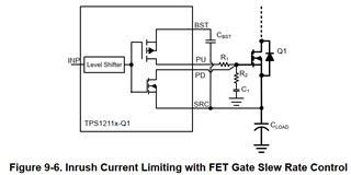
In TPS1211-Q1, how the inrush current is controlled by R1, C1 as per below snap -

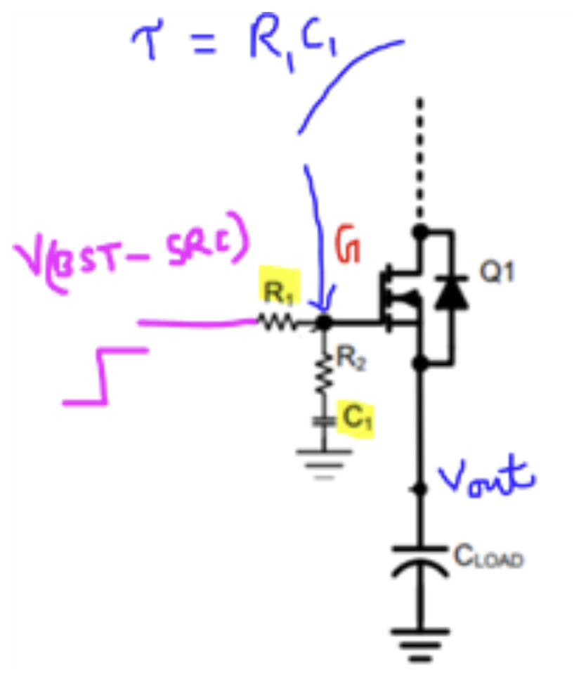
The reason is Cload is connected to the MOSFET source. The CBST capacitor has to discharge to MOSFET G & S.

The C1 should be connected to SRC in order to delay the turn ON of MOSFET. But, in above snap from datasheet, its connected to GND.

So, how inrush through Q1 or how turn ON of Q1 is controlled?

Regards,

Abhishek D.

  • Hi Abhishek,

    If we connect C1 between GATE and SRC, it increases the turn-on delay but does not do dv/dt (slew-rate) control on the GATE. Connecting C1 to ground makes the circuit as source follower.

    V(BST-SRC) is the voltage appears at the PU pin, which charges the GATE VG of Q1 with a time constant of R1C1. As it is a slow ramp-up, the MOSFET Q1 works as source follower with Vout = VG - Vgs_Q1

    Now VG/dt = Vout/dt is controlled by R1C1 

  • Hello, 

    If we connect only R1 (R2 & C1 removed) & increase R1 value (say 100 kohm), then also we can have dv/dt controlled.

    Can you comment on this. 

  • Hi Abhishek,

    Yes. Using just R1 also reduces the gate charging current and slows down the ramp-rate of the GATE voltage.

    BR,

    Rakesh