Other Parts Discussed in Thread: TUSB546A-DCI, TPS65987
Hi team,
There are two questions about the GUI config:
Questions 1:
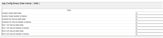
There are port0 and port1 in I2C master config, what is the difference between the two? How to config two slaves by I2C?
Questions 2:
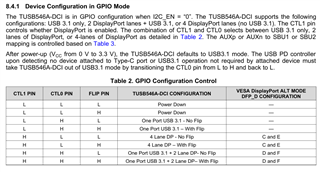
As shown in the datasheet below, after power-on (VCC from 0 V to 3.3 V), TUSB546A-DCI defaults to USB 3.1 mode. The USB PD controller must switch the TUSB546A- DCI moved out of USB 3.1 mode.
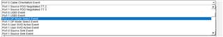
The customer only has DP mode. How to set GPIO in TPS65987?
Thanks for your support.
BR,
Comi