This thread has been locked.

If you have a related question, please click the "Ask a related question" button in the top right corner. The newly created question will be automatically linked to this question.

UCC256404: BW OVP Mode Latch Mode Behavior

Part Number: UCC256404

Hi Team,

Customer chose UCC256404A as the BW OVP Mode is latch mode. That means the RVCC will change to 0 and will keep to 0 when the fault is asserted, right?

After the fault assert, how UCC256404A can go back to work normally?

After fault is asserted, RVCC and VCC will drop down, how about the current source leakage current of HV pin? Is it matched with below EC table?

Best regards

Shuai

  • Hello,

    The RVCC will be disabled on OVP. RVCC is a series pass regulator and when disabled will cut off the supply voltage.  The RVCC capacitor will then discharge based on RVCC loading and is not pulled internally to ground.

    The leakage current on the HV leakage current when the HV startup is not active will be unchanged.

    Regards,

  • Hi Mike,

    My customer Delta is asking if we could change the current limit resistor of HV pin to set the power brown in/out point?

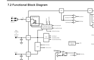
    Do we have any detailed block diagram of HV pin for customer reference?

    Best regards

    Shuai

  • Hello,

    Your inquiry is under review and I will get back to you shortly.

    Regards,

  • Hello,

    The HV pin is a JFET that is used to charge up the VCC capacitor.  It is turned on an off based on VCC UVLO.

    I don't believe this pin can be used for brown in and brown in and brown out.

    The BLK pin can be used to turn on and off the power stage based on the Bulk voltage.  You may be able to use a pull down FET on this pin to disable the LLC.  With external circuitry you could turn off the LLC based on your brownout conditions.

    Regards,