This thread has been locked.

If you have a related question, please click the "Ask a related question" button in the top right corner. The newly created question will be automatically linked to this question.

TPS65130: Unknown issue with negative output

Part Number: TPS65130

Hello. 

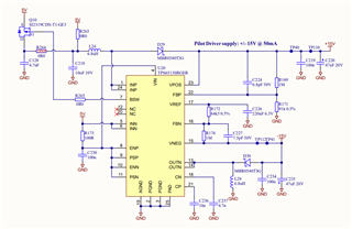
My company has used the TPS65130 in three designs so far, at least three that I am aware of.  We have multiple prototype revisions of two of them.  All told we have nearly 50 individual units with this part included.  We have not had any issues until the latest batch of prototypes on the latest project.  We did a 15 unit proto run.  On two of these 15 units the negative output of the TPS65130 is not regulating.  Output is ~0V.  I have lots of documentation on these designs and of the issue.  So much so I'm not sure how much I can include.  I will post the schematic here.  I also have a spreadsheet that uses the information in the datasheet to calculate the correct values for the passives, but I don't know how to include that. 

It should be said, I did not design this, I was only asked to debug it when the negative output issue arose.  Perhaps I made a mistake, but the spreadsheet I made calculated different values for the circuit than are actually found in our design.  Some of the values look as though they were selected for -10V out.  The design is supposed to provide +15V @50mA and -15V @ 50mA, although the negative output only provides the negative voltage for one, dual op-amp IC that should only draw something like 5mA.  

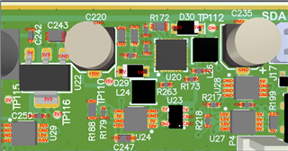
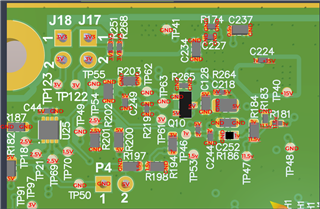
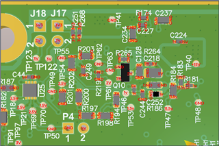
We began the debug by checking for shorted caps and found none.  I checked all the node voltages on a "good" board and a "bad" board, but the only real divergence is the -15V out and then the values on the op-amp pins that require the -15V.  I will include four images that depict this.  I am not sure if the file names show up, but that is how they are differentiated so I may need to redo this if they can't be seen.  (Sorry, this is my first post here at TI.)  The four images are the node voltages on the top and bottom sides of the board on a working and non-working unit, giving four total.

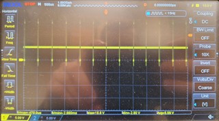
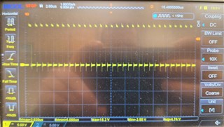
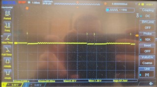
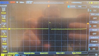
I am also including oscilloscope images (sorry for the poor quality) of the switching on the output of each channel on a non-working board.  The positive 15V output is correct looking, I see the periodic switching that is shown in the datasheet.  The negative 15V output is just low except for some randomly spaced positive 5V pulses that last about 60ns.

Does anyone have any familiarity with an issue like this and how it's resolved?  I have found about 10 different posts on TI forums and similar websites like EEVblog about this specific issue, no negative output on TPS65130, but I don't seem to see any resolutions.  I see a lot of talk about this IC being sensitive to parasitics and layout is very important. 

Thanks in advance!  I will post the images below here.


  • Hi Justin,

    Have you tried to re-solder the "issue" ICs to check whether it is a board assembly issue?

    And have you made any change on the latest prototype compared with your previous project?

    BR

    Patrick

  • Hello!

    Thanks for the quick reply.  On both of the problem boards we first reflowed the IC, then entirely replaced the IC, as well as the diodes, and a few passives.  Whatever the issue is, it is not the component itself.  

    The previous version of this board was designed by my boss's team while they still worked at their previous company.  At that time I was not a part of the team.  That previous company is still operating and I have not yet gotten my hands on the documentation for it.  That said, my boss has assured me that this circuit was not altered in any way, schematically or layout, between revisions.  So, my best answer would be no.

    I spent a day last week with our assembly house and they contacted the board house that fabricated the PCBs looking for their probe docs.  We ordered a run of 15, they fabbed 20 for yield and said three of those were rejected for "opens and shorts".  We have tried, unsuccessfully so far, to get those docs, or at least get them to give us a more detailed explanation than just "opens and shorts".  To me 3/20 seems high, but the assembler said that was on the high end of common, but not un-common.  The units we received all passed the test obviously, and the vendor defends the quality.  The assembler defends their QA and points the finger at the PCB vendor.  I am not sure what to think just yet, but it's hard to blame it on design since the vast majority work.  That said, like I have in the original post some of the passive values seemed off to me.

    Hopefully that info helps.

    Thanks!

    Justin

  • Hi,

    Our expert is out of office and will give you feedback when comes back.

  • Hi Justin,

    You mean 3 boards found the issue, and after you replaced the components including the IC, the issue still exist and follow the boards?

    If so, have you tried to re-solder the IC, which was on the issue boards firstly, to an OK board to see if the -15V will be good? If the same IC on different boards has different results, then we still need to think the issue is followed with the boards.

    BR

    Patrick

  • Yes, that is mostly correct, except it was 2 boards, not 3.  I will try what you suggest.  Since we have tried so many things we were starting to wonder about the boards.

  • Hi Justin,

    Yes, this is what we called A-B-A test, it will help to locate whether the issue should blame the IC or the PCB board.

    BR

    Patrick